
You are using an out of date browser. It may not display this or other websites correctly.
You should upgrade or use an alternative browser.
You should upgrade or use an alternative browser.
-
You can now help support WorldwideDX when you shop on Amazon at no additional cost to you! Simply follow this Shop on Amazon link first and a portion of any purchase is sent to WorldwideDX to help with site costs.
-
A Winner has been chosen for the 2026 July 4th Retevis RA89R Giveaway! Click Here to see who won!
Avanti Sigma4: An alternative view point
- Thread starter bob85
- Start date
I'm completely baffled.
I've tried every piece of coax I've got that is long enough, all tested for integrity - no shorts from shield to center, and all shields and centers unbroken; ends solidly connected.
I've used three different SWR meters, one of which has a scale all the way to 20.1:1 scale.
I lengthened it to 31', I've shortened it to a .64 wave, and tried it as a .75 wave.
I've Isolated the sleeve radials from the mast, and I've kept them all at full ground potential to the main vertical as prescribed. As I said, I've now tried 4 (read FOUR) different gamma matches and the antenna is still sliding around anywhere from 4.1:1 to 10.1:1 SWR from 25.515 to 28.755 MHz.
I am almost angry. I am feeling what must have been the perplexity of those who have been trying to model this elusive antenna.
I do not have the antenna very high, only ten feet up to the feed point from the ground. Maybe this means more to this antenna than it does with most. I read that it ought to affect the TOA, but not likely anything else, however, I am suspicious that it may be a factor locating my tune. To get higher I may have to put together something taller and easily accessible before I can go on - (just guessing . . .), a tip over tower, perhaps.
The only constant difference between now and when I had the original Qv4k on the roof of the house is the foil wrap on the four radials instead of the fiberglass rod supported wires.
Hoo, boy, enough said.
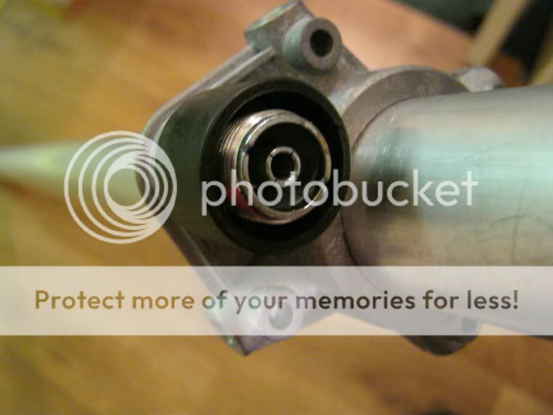
Homer, have you checked the continuity between the center and the shield at the radio end of the feed line?
Are you sure you're seeing an open circuit between the base of the gamma and the rest of the antenna that is at ground?
There is a hub on the radiator right above the gammas dog bone connector to the radiator. This hub looks like a screw
type locking device that is used to secure some telescoping pole devices. I have such a device that makes a 20' foot
aluminum mast when extended, but it does not provide continuity across the hubs. These hubs might have a tapered
sleeve made of a non-conductor inside that makes the secure connections for each segment. Check the continuity across that hub.
Homer:
I am BY NO MEANS an antenna expert.
But - as an observer - I see the radials are very, very close to the center radiator near the bottom. Aren't they supposed to be farther away from the center radiator - like the original assembled Sigma picture shows?
I see you are using aluminum foil wrapped on some 'material' for the radials too; could it have some capacitive properties?
Perhaps some cheap electrical conduit can replace this.
http://www.cbtricks.com/ant_manuals/avanti/av174/graphics/sigma4_av174_om.pdf
Dos centavos...

homerbb,
don't be angry, you are not alone in having trouble understanding the sigma design, i certainly don't fully understand it ,
,
i can see a couple of areas in your homebrew that may look ok if you were dealing with something simple like a groundplane antenna but you are not,
you stepped into the twilight zone, the outer limits, a place beyond 5/8,
the place CEBIK said he would rather not go
"because people don't understand" the currents that flow,
a gamma is not just a conductor and a lossy series capacitor to cancel reactance,
the gamma and central monopole form a transmissionline shorted at the far end,
this transmissionline has currents that flow in two directions, antenna currents and contra flowing transmissionline currents,
the transmissionline mode impedance and currents are effected by tube diameter ratios length and spacing, gamma rod diameter also effects sytem Q,
all the gamma articles i have found so far only deal with parallel conductors,
look at your design, compare it to the sigma and vector, from the pics it looks like you need a thinner gamma and it needs to be closer at the bottom so it tapers outwards like the original,
the stock 7/8 vector gamma use
tube
.512" x
.049" x
14-3/8" ( not including the 1-1/4" fold )
rod
.236" x
34"
maximum capacitance ) is 50pf
the radial sleeve around the central monopole also forms a transmissionline whos impedance is determined by tube diameter ratios/length and spacing/taper,
moving the radial sleeve closer to the monopole lowers transmissionline mode impedance/raises transmissionline mode current in sleeve monopoles but has little effect on the monopole antenna mode impedance,
closer radial spacing also raises the resonant frequency of the system,
info on transmissionline mode currents in sleeve monopoles is dealt with in the arrl but again it deals only with parallel radials forming parallel transmissionlines, i am not sure how much bearing this has on the sigma design as compared to open sleeve antennas,
look again at your design, the radials are too closely spaced at the bottom and parallel to the monopole,
the radials should be straight from 1.5" spacing at the base to 15" or so spacing at the 90" point up the radial sleeve,
good luck
don't be angry, you are not alone in having trouble understanding the sigma design, i certainly don't fully understand it
,i can see a couple of areas in your homebrew that may look ok if you were dealing with something simple like a groundplane antenna but you are not,
you stepped into the twilight zone, the outer limits, a place beyond 5/8,
the place CEBIK said he would rather not go
"because people don't understand" the currents that flow,
a gamma is not just a conductor and a lossy series capacitor to cancel reactance,
the gamma and central monopole form a transmissionline shorted at the far end,
this transmissionline has currents that flow in two directions, antenna currents and contra flowing transmissionline currents,
the transmissionline mode impedance and currents are effected by tube diameter ratios length and spacing, gamma rod diameter also effects sytem Q,
all the gamma articles i have found so far only deal with parallel conductors,
look at your design, compare it to the sigma and vector, from the pics it looks like you need a thinner gamma and it needs to be closer at the bottom so it tapers outwards like the original,
the stock 7/8 vector gamma use
tube
.512" x
.049" x
14-3/8" ( not including the 1-1/4" fold )
rod
.236" x
34"
maximum capacitance ) is 50pf
the radial sleeve around the central monopole also forms a transmissionline whos impedance is determined by tube diameter ratios/length and spacing/taper,
moving the radial sleeve closer to the monopole lowers transmissionline mode impedance/raises transmissionline mode current in sleeve monopoles but has little effect on the monopole antenna mode impedance,
closer radial spacing also raises the resonant frequency of the system,
info on transmissionline mode currents in sleeve monopoles is dealt with in the arrl but again it deals only with parallel radials forming parallel transmissionlines, i am not sure how much bearing this has on the sigma design as compared to open sleeve antennas,
look again at your design, the radials are too closely spaced at the bottom and parallel to the monopole,
the radials should be straight from 1.5" spacing at the base to 15" or so spacing at the 90" point up the radial sleeve,
good luck
Yes. I've checked it all the way from radio to antenna.Homer, have you checked the continuity between the center and the shield at the radio end of the feed line?
Yes, I tested this too. There is no direct ground from the center of the coax connector to the antenna. There is a connection only from the center to the sleeve of the gamma. I took the connector apart to reassure myself of this as well.Are you sure you're seeing an open circuit between the base of the gamma and the rest of the antenna that is at ground?
I provided for this throughout the length of the antenna by securing each section to the other with screws. Remember, this antenna has provided excellent service for me as a 5/8 wave, and been tunable as the prior Qv4k I am trying to improve. Nevertheless, I will go back over the whole length of it checking the continuity from section to section.There is a hub on the radiator right above the gammas dog bone connector to the radiator. This hub looks like a screw
type locking device that is used to secure some telescoping pole devices. I have such a device that makes a 20' foot
aluminum mast when extended, but it does not provide continuity across the hubs. These hubs might have a tapered
sleeve made of a non-conductor inside that makes the secure connections for each segment. Check the continuity across that hub.
Homer, If i was on a boat in the middle of the ocean and the motor stopped running, and had NO spare parts...... I would look for YOU to come make it run....you have an uncanny knack of finding ways to make the materials at hand work somehow.
73
Jeff
As we said in the oil patch, all we need is soft line and sash cord. a little duct tape goes a long way, too.
")
Homer:
I am BY NO MEANS an antenna expert.
But - as an observer - I see the radials are very, very close to the center radiator near the bottom. Aren't they supposed to be farther away from the center radiator - like the original assembled Sigma picture shows?
I see you are using aluminum foil wrapped on some 'material' for the radials too; could it have some capacitive properties?
Perhaps some cheap electrical conduit can replace this.
http://www.cbtricks.com/ant_manuals/avanti/av174/graphics/sigma4_av174_om.pdf
Dos centavos...
You are observant, and your thinking is running along the same line right now as my own. I included the piece in my previous post that the only change to the antenna that is constant regardless of the changes I made is the foil tape covered radials. I hoped to see if someone else expressed some possible misgivings over the radials.
I can easily get the bottom mount points further away from the center radiator, That I will try first. If I must I will replace them. It's on the short list of things to try.
Thanks everyone!
Last edited:
homerbb,
don't be angry, you are not alone in having trouble understanding the sigma design, i certainly don't fully understand it
i can see a couple of areas in your homebrew that may look ok if you were dealing with something simple like a groundplane antenna but you are not,
you stepped into the twilight zone, the outer limits, a place beyond 5/8,
the place CEBIK said he would rather not go
"because people don't understand" the currents that flow,
a gamma is not just a conductor and a lossy series capacitor to cancel reactance,
the gamma and central monopole form a transmissionline shorted at the far end,
this transmissionline has currents that flow in two directions, antenna currents and contra flowing transmissionline currents,
the transmissionline mode impedance and currents are effected by tube diameter ratios length and spacing, gamma rod diameter also effects sytem Q,
all the gamma articles i have found so far only deal with parallel conductors,
look at your design, compare it to the sigma and vector, from the pics it looks like you need a thinner gamma and it needs to be closer at the bottom so it tapers outwards like the original,
the stock 7/8 vector gamma use
tube
.512" x
.049" x
14-3/8" ( not including the 1-1/4" fold )
rod
.236" x
34"
maximum capacitance ) is 50pf
the radial sleeve around the central monopole also forms a transmissionline whos impedance is determined by tube diameter ratios/length and spacing/taper,
moving the radial sleeve closer to the monopole lowers transmissionline mode impedance/raises transmissionline mode current in sleeve monopoles but has little effect on the monopole antenna mode impedance,
closer radial spacing also raises the resonant frequency of the system,
info on transmissionline mode currents in sleeve monopoles is dealt with in the arrl but again it deals only with parallel radials forming parallel transmissionlines, i am not sure how much bearing this has on the sigma design as compared to open sleeve antennas,
look again at your design, the radials are too closely spaced at the bottom and parallel to the monopole,
the radials should be straight from 1.5" spacing at the base to 15" or so spacing at the 90" point up the radial sleeve,
good luck
I can take care of this, too. These suggestions seem to be the core of the discussion re my homebrew so far. I used a gamma similar to what you describe (not pictured, yet) except the outer sleeve is longer (too long) according to your provided dimensions.
I can fix the mount point of the gamma and bring it in closer as well.
Robb centered on the potential problems of my radial sleeve spacings. I'll tend to that, too.
I haven't the knowledge nor the RF tools many of you possess, only empirical application - put it together and make it work. I am getting a little mad scientist over this thing not to mention I am out on a limb with my pride now.
Thanks so much for your input.
I have to work today, so not much can be done. Maybe tomorrow and Monday I can return to this beast and slay it.
I want to say thanks to everyone, Bob, Homer, Marconi, Shock, Robb, everyone, all of you guys.
This is an incredible thread, the more I read this, the more I realize how valuable it is, The info you guys share, the work everyone is doing, homer`s pictures, marconi`s thoughts and questions...the list goes on.
I am looking forward to 007`s build and see what he discover`s as well
I am going to sticky this thread to the top.
I was thinking it would also be great to see if some one from Sirio would like to have a look at the work that is going on here......
73
Jeff
I'm not sure I've have the answer to this problem but I have some observations from my FM antennas. It is true that the placement and diameter of the gamma match can shift the impedance. I have used gamma matches on this design that ranged from 3/8 to 1 inch diameter and could always find a perfect match. On the high power models I use a large diameter gamma to accommodate the Teflon insulator. The antenna also uses a DIN connector that must be spaced out from the base of the antenna so that hardline can be used. This places a fat gamma almost parallel to the radiator and still shows no problems with matching or performance. Tilt it too close to the radials and that will mess things up quickly.
One question I have is what material is the round radial support disk made from? I'm talking about the disk with the four holes that the radials pass through. I assume this is an insulator because it can not be conductive. Also when tuning your gamma do you find the lowest VSWR with the match set at any of it's extremes? For example, is the rod all the way inserted into the lower tube? Is the tap point between the gamma and main radiator all the way at the top of the gamma rod? Does the antenna have a good VSWR on any frequency you can check?
Your radials do look too close to the radiator at the base. Bend the four large wire connectors you have holding the radials at the base so the radials maintain the same angle all the way to the loop. I don't think adding spacers here will help. It has more to do with the sharper angle in the lower part of the radials due to the bend. Your wire connectors place the base of the radials parallel to the radiator. Bending the connectors to match the desired angle of the radials will improve this. Although it still may not be the entire problem.
Making a gamma with a 36 inch 3/8 rod and 10 inch 1/2 tube should have more then enough capacitance and length to match this antenna. The tap point from rod to radiator is typically around 27 inches up from the connector bracket. If you correct the angle of the radials at the base, your radial support disk is an insulator, and your gamma is close to these specs, I'm at a loss as to why you can't match it. You can change element lengths on this antenna by feet, making the antenna completely ineffective but yet the gamma can still be tuned to provide a perfect match in nearly every case.
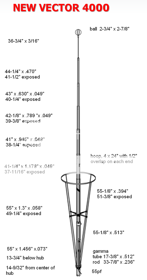
Thanks Bob. I know that you told us the New Vector was shorter, but I'm really surprised it is less that 27' feet @ the middle of the CB band. I think I miss judged the length by a foot or more at 27.185. The gamma sleeve is longer than I thought also.
Last edited:
dxChat
- No one is chatting at the moment.