They once were lost but now they're found. Got a question that prompted me to search for these pics, and somehow overlooked them. Figured they were a casualty of the last hard-drive crash ten years ago or so. Naturally I found them looking for something else.
Here is a procedure we apply to every Browning Mark 3 receiver that we service. The band selector may only have one tuneable band, and two "fixed" receiver frequency choices marked "XTL1" and "XTL2". Or it may be the later version with two tuneable bands, and only one fixed receiver crystal.
These pics are part of the conversion from the older one-band to newer two-band receiver. Most of our customers want to be able to hear above channel 27. Barkett sells the 31.72 MHz crystal needed for this expansion, along with a new receiver dial and the all-important "banjo" washer where the band crystals get their ground connection.
Just the same, none of our clients has used a fixed receive-frequency crystal since 1976. A local plumber had a FCC business license for 27.320 MHz. Had one-channel mobile radios in his service trucks, along with the LEGAL 100-Watt mobile linear his license allowed. Along came 40 channels, and his private business channel was now halfway between channel 31 and 32. He soon gave up and upgraded to Motorola FM business radios.
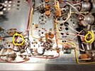
Anyway, the hookup on the rear of the selector, called "SW2" in the schematic has two mica capacitors mounted on it, and the tuning coil L5 used for dial calibration also connected through it. This is necessary to make a crystal work on the same oscillator circuit that uses the coil and tuning dial.
Just one problem. Any funny business in any of the switch contacts in SW2 cause the dial frequency to drift or jump. Or both.
I adopted a policy years ago to ditch the fixed-crystal circuit altogether, and hard-wire SW2 for tuneable receive only. Back in the day, adding a third tuneable band below channel 1 was popular, and that made this procedure necessary. Or at least attractive. No other way to use that third click of SW2 for a tuneable band.
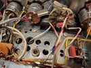
Here is the rear of SW2 in an old-style receiver that had only the one tuneable band. One lug where the two mica caps connect is already being desoldered. The white wire with the red stripe has already been unhooked. We won't be using that wire.

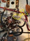
First one to come loose is C52B. It's the one that has one leg soldered to a ground lug to the rear of SW2.

Take the loose end of C52B and follow the white/red wire to a tie strip lug between SW2 and V4 socket. Remove the white/red wire from this lug and insert the free end of C52B. Don't solder it yet.
Now *carefully* remove C51A from the rear of SW2. If you break on lead wire from it you'll need a new cap. Just be nice.

C51 is now strung from the tie-strip lug closest to V4 to pin 2 of V4. It may not reach, but can be lap-soldered to one of the component leads that already connect that tie-strip lug to V4 pin 2.

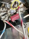
There is another white wire with a red stripe from V4 pin 2 to SW2. Cut the SW2 end of this wire so it's still attached to V4 pin 2. There is a white wire with a blue stripe coming from topside tuning coil L5 to the SW2. Cut it at SW2. Now shorten each of these wires, or just one of them if you like so they can be stripped and lap-soldered together.

I always slide insulating sleeve over the splice. Probably not necessary, but we do it anyway.
The pics show no band crystals. For an old one-band Mark 3, installing them would be next. But I have work to do today. That part of the story will have to be part 2. If your radio already has two tuneable bands, you're done. This should fix quirky dial-stability problems, or at least reduce them.
73
Here is a procedure we apply to every Browning Mark 3 receiver that we service. The band selector may only have one tuneable band, and two "fixed" receiver frequency choices marked "XTL1" and "XTL2". Or it may be the later version with two tuneable bands, and only one fixed receiver crystal.
These pics are part of the conversion from the older one-band to newer two-band receiver. Most of our customers want to be able to hear above channel 27. Barkett sells the 31.72 MHz crystal needed for this expansion, along with a new receiver dial and the all-important "banjo" washer where the band crystals get their ground connection.
Just the same, none of our clients has used a fixed receive-frequency crystal since 1976. A local plumber had a FCC business license for 27.320 MHz. Had one-channel mobile radios in his service trucks, along with the LEGAL 100-Watt mobile linear his license allowed. Along came 40 channels, and his private business channel was now halfway between channel 31 and 32. He soon gave up and upgraded to Motorola FM business radios.
Anyway, the hookup on the rear of the selector, called "SW2" in the schematic has two mica capacitors mounted on it, and the tuning coil L5 used for dial calibration also connected through it. This is necessary to make a crystal work on the same oscillator circuit that uses the coil and tuning dial.
Just one problem. Any funny business in any of the switch contacts in SW2 cause the dial frequency to drift or jump. Or both.
I adopted a policy years ago to ditch the fixed-crystal circuit altogether, and hard-wire SW2 for tuneable receive only. Back in the day, adding a third tuneable band below channel 1 was popular, and that made this procedure necessary. Or at least attractive. No other way to use that third click of SW2 for a tuneable band.
Here is the rear of SW2 in an old-style receiver that had only the one tuneable band. One lug where the two mica caps connect is already being desoldered. The white wire with the red stripe has already been unhooked. We won't be using that wire.
First one to come loose is C52B. It's the one that has one leg soldered to a ground lug to the rear of SW2.
Take the loose end of C52B and follow the white/red wire to a tie strip lug between SW2 and V4 socket. Remove the white/red wire from this lug and insert the free end of C52B. Don't solder it yet.
Now *carefully* remove C51A from the rear of SW2. If you break on lead wire from it you'll need a new cap. Just be nice.
C51 is now strung from the tie-strip lug closest to V4 to pin 2 of V4. It may not reach, but can be lap-soldered to one of the component leads that already connect that tie-strip lug to V4 pin 2.
There is another white wire with a red stripe from V4 pin 2 to SW2. Cut the SW2 end of this wire so it's still attached to V4 pin 2. There is a white wire with a blue stripe coming from topside tuning coil L5 to the SW2. Cut it at SW2. Now shorten each of these wires, or just one of them if you like so they can be stripped and lap-soldered together.
I always slide insulating sleeve over the splice. Probably not necessary, but we do it anyway.
The pics show no band crystals. For an old one-band Mark 3, installing them would be next. But I have work to do today. That part of the story will have to be part 2. If your radio already has two tuneable bands, you're done. This should fix quirky dial-stability problems, or at least reduce them.
73
Last edited: