• You can now help support WorldwideDX when you shop on Amazon at no additional cost to you! Simply follow this Shop on Amazon link first and a portion of any purchase is sent to WorldwideDX to help with site costs.

Browning Mark 3 receiver. Even-older dog learns a new trick.

nomadradio

Analog Retentive
I Support WorldwideDX.com!
Apr 3, 2005
8,937
15,009
698
Louisville, KY
www.nomadradio.com
Adding lower channels to the Browning Mark 3 receiver requires a 31.1 MHz crystal and some rewiring. Gonna use the same module I showed for the Mark 4A.

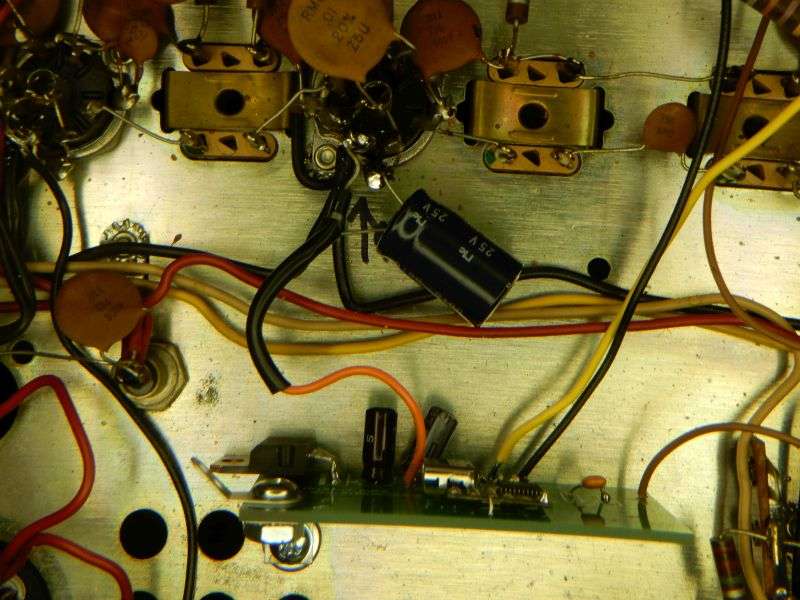
Adapting the ProgRock module to the Browning Mark 3 receiver is a bit more involved than the Mark 4A receiver. To start, it needs to rectify and filter its own source of DC power. Not a big deal, the rectifier diode taps the 6.3 Volt AC heater power. The filter cap gets the negative lead grounded.
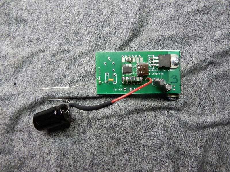
gBWqqu.jpg


It mounts in one of the vent holes in the deck. Flat washers keep the nut from falling through the hole.
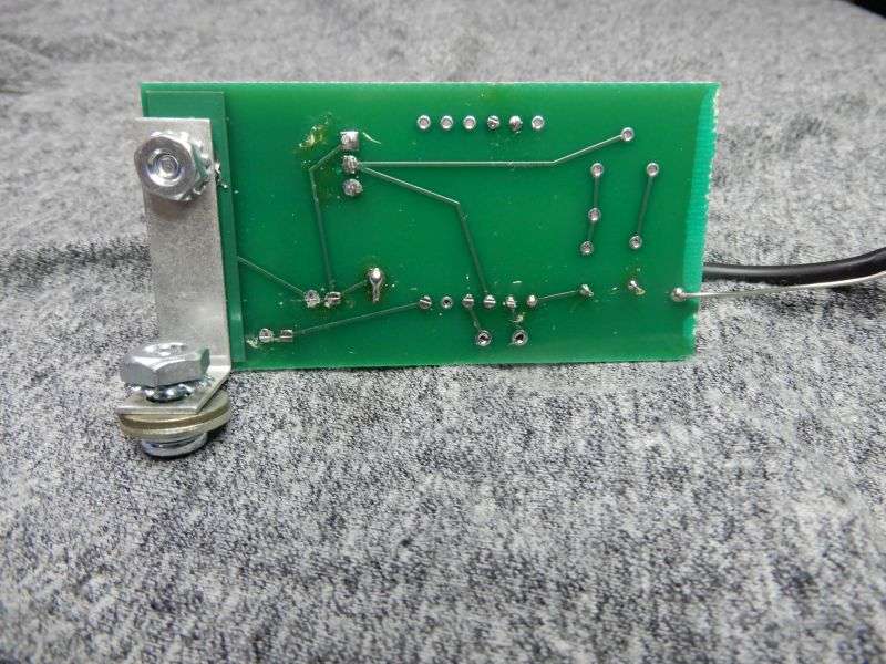

m4Z6lX.jpg


The tricky part is rewiring the front-panel band/crystal selector. The fixed-crystal receive feature gets removed altogether, so it has three tuneable bands.

Gotta dig out a photo model of each Mark 3 receiver version. The first one from 1970 had only one tuneable band and two fixed receive crystal sockets. The later version had two tuneable bands and one fixed crystal socket. The nitty-gritties of the modificaton are not quite the same. Need to shoot pics of each version. Removing the fixed-crystal feature from the Mark 4A is a lot easier. Remove one wire, shorten another and solder it to the foil pad where the removed wire was.

That's the next step, detailed instructions with pics.

No rest for the wicked.

73
 
  • Like
Reactions: AudioShockwav

Adding a second or third tuneable receive band to the *original* version of the Browning Golden Eagle Mark 3 receiver requires bypassing the factory circuits meant for receiving a fixed frequency using a 4 (or so) Mhz crystal. This was to use it as a business radio. Your plumbing trucks would have 3-channel radios and the base would be stuck on the crystal channel. That way the receptionist can't bump the tuning knob and miss a truck calling in. Since this version has only one tuneable band, there is only one band crystal, 31.4 MHz soldered directly to V3. The later version of this receiver had two band crystals, to tune channels above 27 and only one fixed-crystal socket.

Rather than install two new quartz crystals to add upper and lower channels to the first-version Mark 3 receiver we'll be installing a DDS module that delivers 31.4 MHz for channels 1-27, 31.72 MHz for channels 28-59 and 31.08 MHz for 26.645 to 26.955.

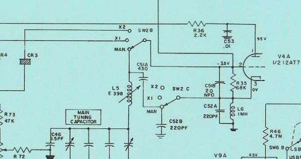
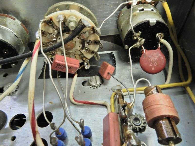
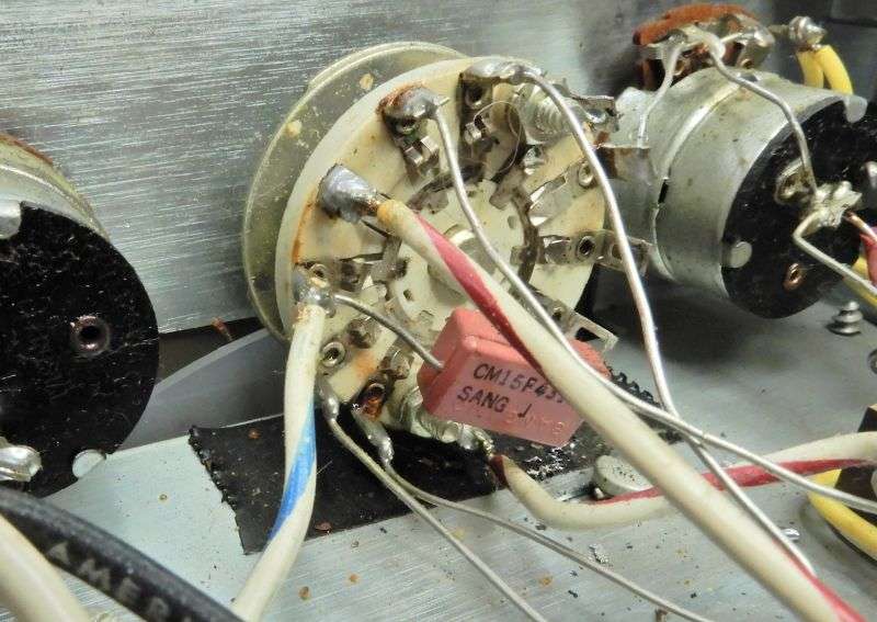
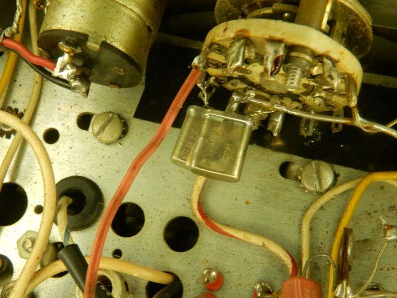
There are two molded-mica capacitors on the rear of the CB/Xtal switch. They are C51A and C52B. They get switched out of circuit for crystals, and switched into the circuit for a tuneable band.

cFRHUu.jpg


We need to remove them from the selector and hard-wire the circuit for three tuneable bands. Here's the before pic.

H5ZZcl.jpg


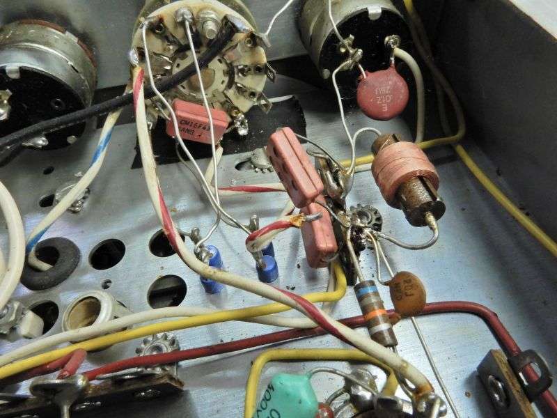
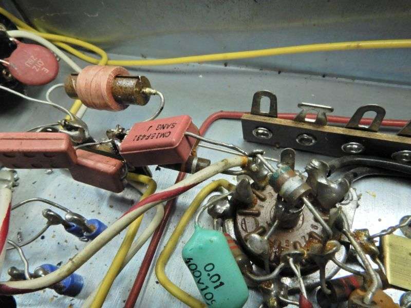
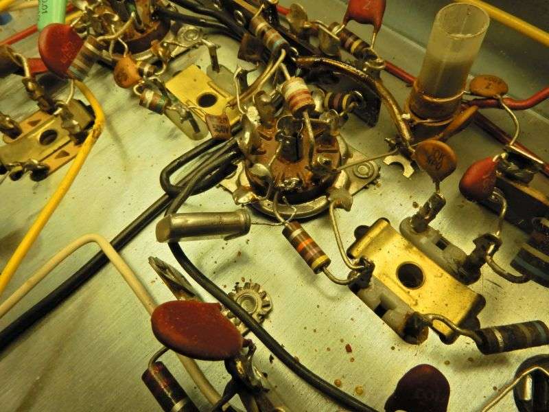
C52B is the easy one, it has one lead connected to the ground lug of the tie strip to the right of the selector. C52B gets unhooked from the selector. There is a white/red wire leading to the rear-most lug of the adjacent tie strip. The wire gets unhooked from the tie strip, and the loose end of C52B gets soldered to the lug in place of the white/red wire. This places it directly in parallel with L6, the fat 1 mHy RF choke.

dwg0az.jpg


The next part is a it more fiddly. C51A has to come loose from the selector. Doing this without breaking off a lead wire is easier said than done.

Oim2ni.jpg


Assuming it came away in one piece, solder one end of C51A to the rear-most end of the 3-terminal tie strip next to V4.

Solder the other end of C51A to pin 2 of V4. There's another white/red wire also on that pin of V4.

GhdO8u.jpg


I'll be packing a 430pf silver-mica cap with the kit for this mod. Dial calibration will be thrown off less by using the original capacitor. And if a leg breaks off, including a 430pf cap in the kit will prevent tragedy.

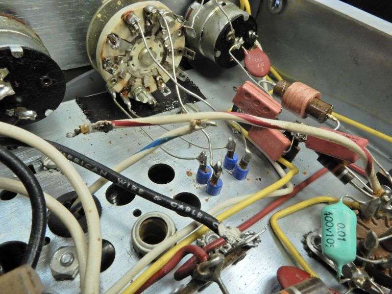
The white/red wire from V4 pin 2 gets cut loose from the selector. It was unsoldered in the pic, but clipping it next to the selector is easier. The white/blue wire leading to the slug-tuned coil L5 on the top side of the chassis also gets cut.

bXuATD.jpg


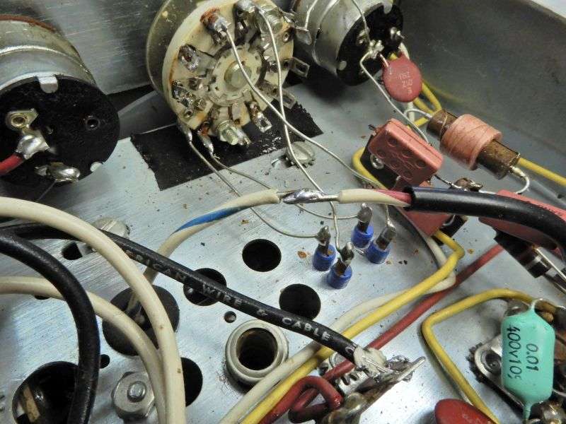
They get shortened and stripped to get lap-soldered together. This is why you don't need to unsolder them from the selector. You'll have plenty of length just clipping them loose.

NFHjQx.jpg


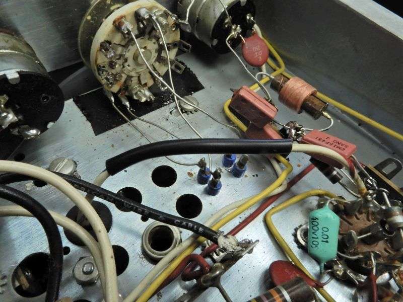
Naturally the splice should get insulated.

eVRb4X.jpg


Oddly enough the schematic calls this 31.4 MHz crystal "CR".

Ns3EAn.jpg


It comes completely loose from V3 pin 2.

Now it's my bedtime. I'll pick up where I left off next chance I get.

73
 
Last edited:
Now for the rest of the story. The front-panel band selector has been reconfigured for three tunable bands. The original crystals get removed if that's where they were found. We left off at V3. Either a single crystal gets removed from there, or you'll find a long solid wire that leads from V2 pin 3 up to the front panel. That wire is red in this pic. The crystals both come loose.

OXJXaw.jpg


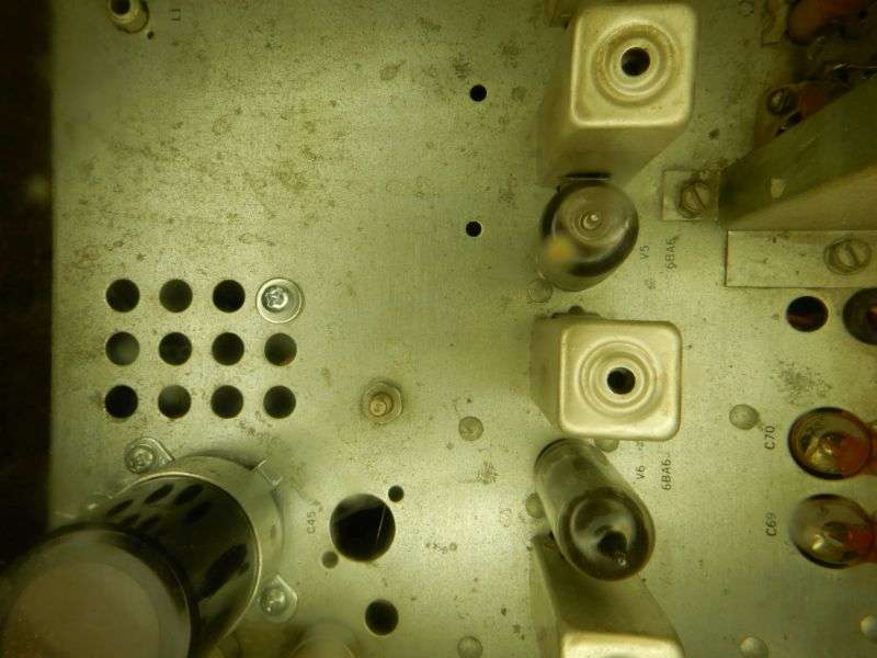
The module gets bolted to the underside of the chassis in the front-outer side vent hole.


TgwVMf.jpg


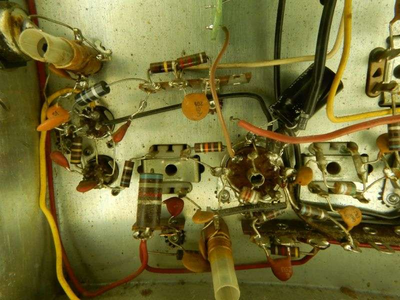
The ProgRock board gets mounted in a single vent hole, with a flat washer on top and bottom side of the chassis. This pic shows the red power lead with the rectifier on pin 3 of V5 and the filter cap grounded to the tube's mount saddle.

Av3QH2.jpg


This vent hole.

The wire that goes from V3 pin 2 to the band switch comes loose and gets soldered to ground. This pic is from a different receiver and tapped pins 4&5 to power the pc board.

The brown wire from the module goes to pin 2 of V3, either where the single crystal was, or the long wire to the front panel.

QCWkGM.jpg


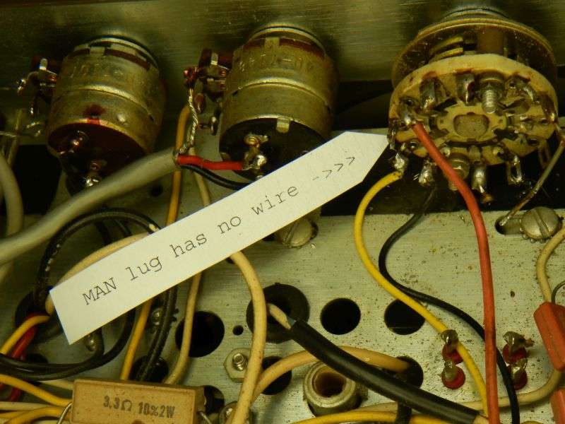
If your receiver is the old one, and never was converted to hear above channel 26, you won't have this long wire from the selector back to V3 pin 2. If so, you need to add a ground wire from the common lug seen here with the red wire on it.

2mVzLE.jpg


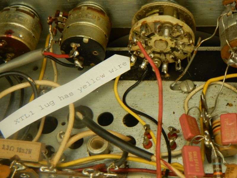
This also demonstrates that an adapter board that selects three output frequencies only needs two wires to do this. The switch contact for the "Tun" or "CB" position of the switch has no connection on it.

There should be a yellow and a blue wire on the module that will reach to the front panel, and this switch. The yellow wire serves to select the "HF" or "XT1" center position of the switch. This will now cover channels 28 to 59.

DUnEWA.jpg


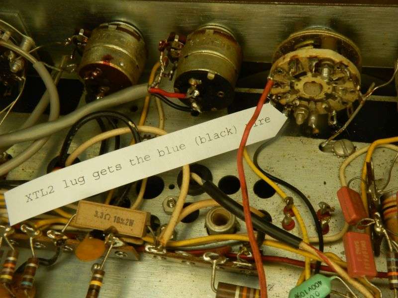
The lower channels are on the far-right click of the selector. A black wire serves in place of a blue wire today. I misplaced the spool of blue hookup wire.

li61tX.jpg


In the end the setup ends up the same for either receiver version, the one with two fixed-channel crystal sockets, or the later receiver with only one crystal socket.

The receiver should now have all three bands functioning. Tweaking the front end alignment to broadband it will be your problem.

73
 
Last edited:
  • Like
Reactions: AudioShockwav

dxChat
Help Users
  • No one is chatting at the moment.