
Here's another relay swap for a tube radio. This time the Browning Mark 3 SSB transmitter. The original relay is powered from about 300 Volts DC. The relay's coil is in series with a 10-Watt 22k resistor that takes about 200 Volts of the total, leaving about 100 Volts across the relay coil when you key the mike.
And that's what the relay coil is built to require. 100 or 110 Volts DC. The Amphenol 80MC2 mike plug presents a unique hazard. It was meant for mike cords that had a robust braided shield. It gets captured between the metal body of the plug and the relief spring, under a set screw. Just one problem. Sooner or later the braid will fray, strand by strand until the cord's ground connection comes completely loose inside the plug.
Where you can't see it.
When this happens, the body of a metal base microphone becomes hot with about 300 Volts DC when you key it. And if you touch grounded metal while it's keyed, your body becomes the path to ground for current through the relay coil.
Not pleasant. Not safe. Especially not for a heart patient.
More-modern mike cords have a tiny, wimpy shield that won't hold up for a week. You can 'double up', and wire several unused conductors in the mike cord in parallel with the shield, but the mechanical-weakness problem remains.
This is the procedure we use to modify the transmitter to use a 12-Volt DC relay.
Bad news is we won't cover rewiring the contact pins of the socket. The original relay uses a unique layout of the pins. It was discontinued at least 30 years ago. To use the more-modern "ice-cube" size relays you can actually buy, the socket has to be changed to the newer type.
And put every wire but two onto a lug that's in a different position from the old one. The two coil pins are positioned the same as on the old socket.
That was already done to this radio, using a "KHU" type relay with a 110-Volt DC coil like the original.
All we cover here is the conversion to use a relay with a 12-Volt DC coil. We will borrow some of the 6.3-Volt AC that powers the heaters in the tubes and the pilot lights. The added current drain will not be significant. A half-wave voltage doubler circuit will get us about 16 Volts DC. The transistor will lose about 2 Volts of this. 14 Volts on a 12-Volt relay coil won't cause any trouble for the first few hours that it stays keyed. You could put a 22-ohm resistor in series with the coil of the new relay if that makes you feel better about it. A PNP transistor serves to reduce the current that the mike cord and switch will have to carry. Reduces the risk of hum or noise being added to the mike audio, especially if the mike cord is getting old.
Here are the parts you'll need. All but the 1-ohm quarter-Watt fuse resistor. Forgot to put it in the pic, didn't feel like reshooting it for something that lame.
Mk3_12Vrelay_Parts
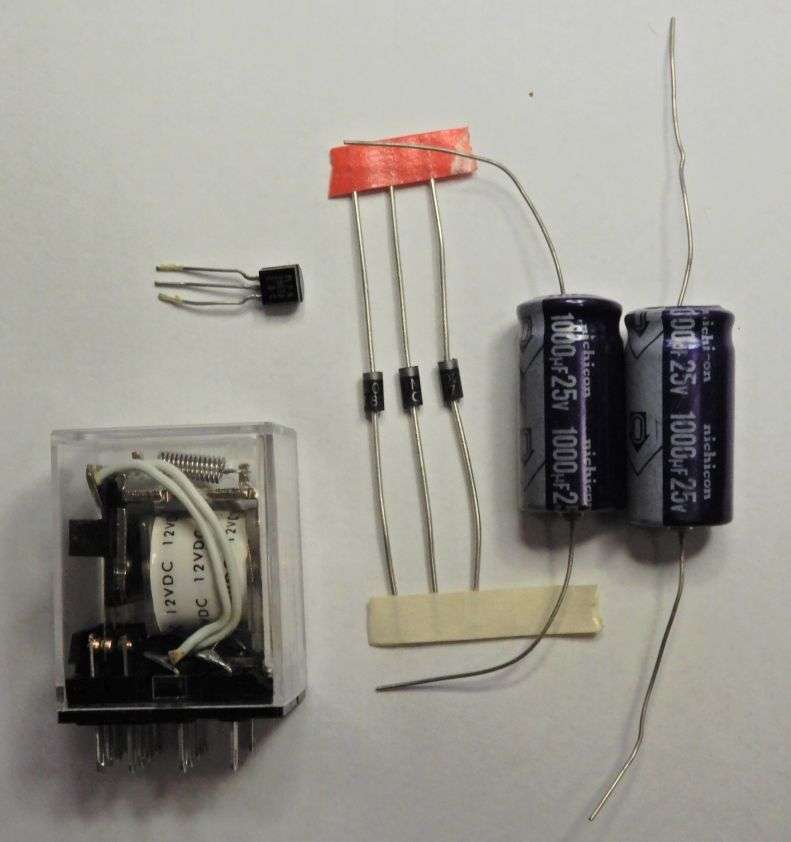
Just about any generic PNP transistor rated for more than a quarter of an Amp is suitable for this. The 2N2907A/PN2907A is the same on used to key the relay in a Texas Star amplifier, and should not be tough to track down. I use it because we have them handy. TS amplifiers tend to consume a lot of keying transistors.
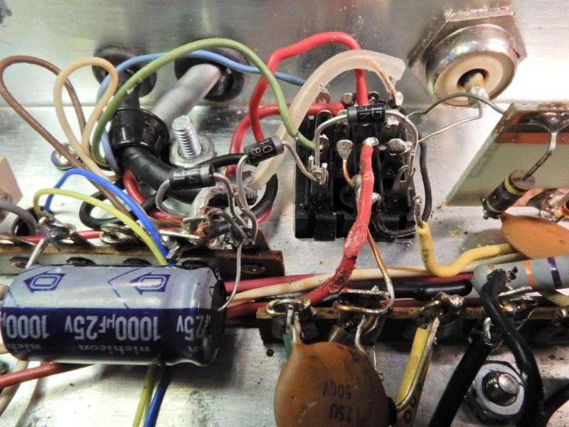
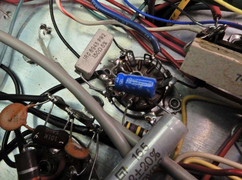
Here is the original current source for the relay coil, R62.
Mk3_12Vrelay_B4
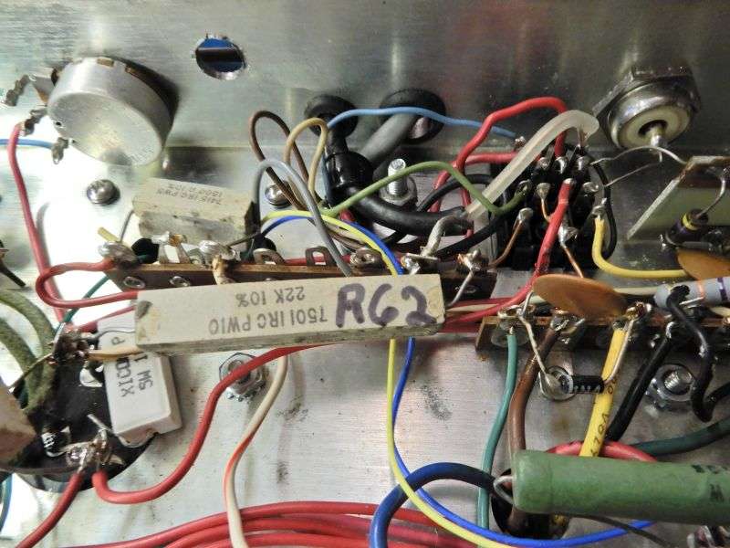
Remove R62 completely, and the wire running from the tie point to the "hot" coil lug of the relay socket. Also unsolder the yellow wire from the "cold" side coil lug on the relay socket. Clear the solder from all three, the tie point and both relay-socket lugs.
Mk3_12Vrelay_PullR62
First mount the input capacitor and fuse resistor. There are spare lugs on this tie strip available as you see here. You can solder the lug where the cap meets the resistor, but don't solder anything else yet.
Mk3_12Vrelay_1st_cap
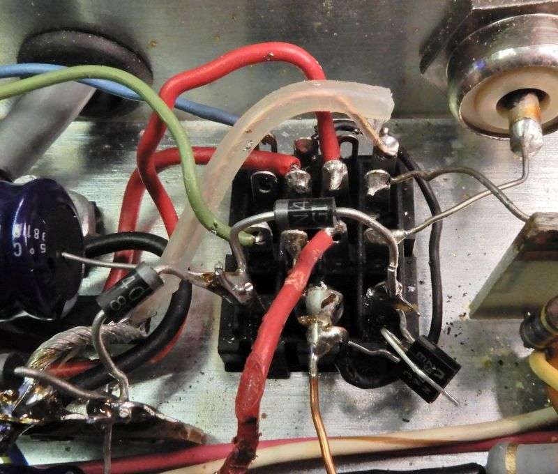
Next add the 3 rectifier diodes as seen here. The direction they "point" matters, indicated by the end with the stripe on each one. Feel free to wrap the lead from the NON-banded end of the left-most diode around the ground braid. Not worth the trouble to heat up all the solder on this ground lug just to poke the lead into the hole. Odds are there's no room for it, with the fat braid taking up the space. Just be sure the wrapped-around lead is soldered to the braid securely. Feel free to solder the lug on the tie strip where two diodes and the capacitor all meet.
Mk3_12Vrelay_3diodes
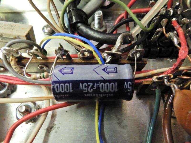
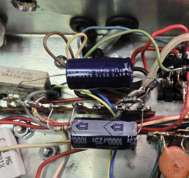
Insert the positive lead of the second capacitor into the "hot" coil lug of the relay socket. The one with two diodes already on it. Solder this lug now. The negative end of the cap goes into a handy ground on the tie strip. Solder it, too.
Mk3_12Vrelay_2nd_cap
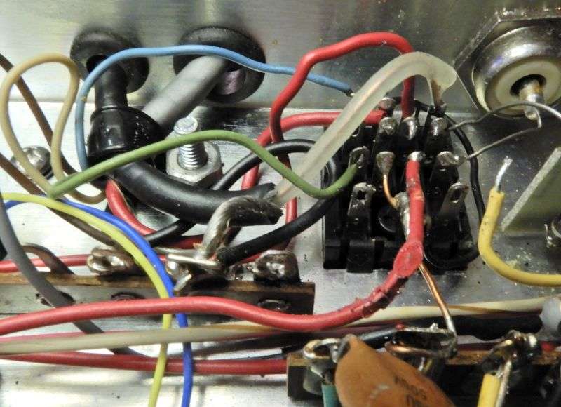
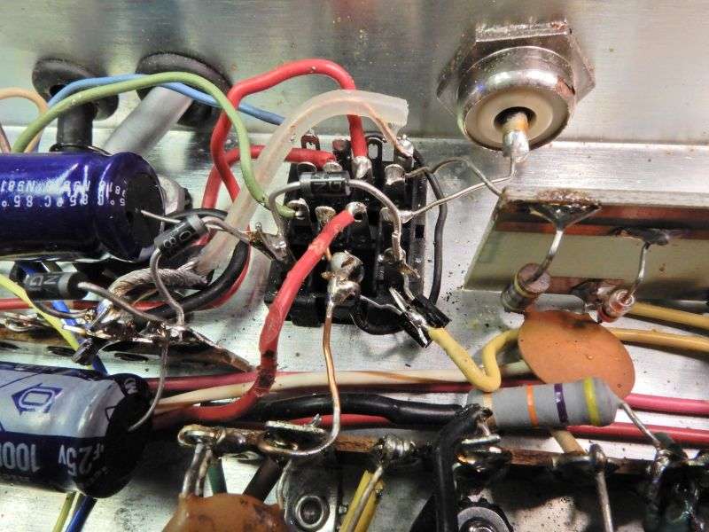
Now it's time for the transistor. The emitter lead goes to the "cold" side relay-socket lug. The collector goes to the ground wire on the relay socket. A wrap-around connection is okay here, too.
Mk3_12Vrelay_trans
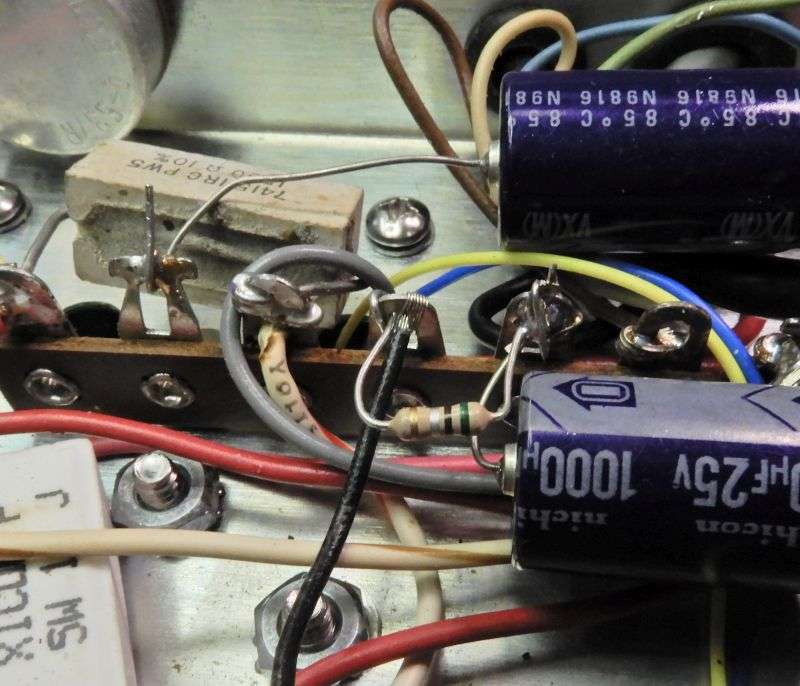
It's time to strip the end of the yellow keying wire that leads to the mike socket. Bend the center base-terminal wire of the transistor back so it's parallel to the stripped end of the yellow wire. Hold the base-lead wire with needle-nose or other tool so the actual bend is away from the plastic body. Simply bending the lead back with your fingertip will cause the bend to occur against the plastic body of the transistor. Bad idea. Makes the bend too sharp. The lead wire will crack and fall off flush with the black plastic.
Lap solder the end of the yellow wire to the center base lead of the transistor.
Mk3_12Vrelay_trans2
Now you'll need a black wire about 6 inches long, stripped at both ends. Small wire like #24 is fine, since the current will be low. Solder one end to the fuse resistor.
Mk3_12Vrelay_black_wire_1
Now solder the other end to the tube socket closest, the 6BQ5. Pin 4 already has a black wire on it. That's where this one goes, the 6.3 Volt AC power feeding the tube's heater.
Mk3_12Vrelay_black_wire_2
Check your work. Remember the old carpenter's advice, "Measure once cut twice. Measure twice cut once".
Naturally this makes putting a standard 4-pin mike socket in place of the original 2-pin much safer. No more exposed high voltage on the end of pin 3. Of course, this would only be dangerous when the radio is powered without a mike plugged in. Not a big deal, but real.
Naturally I'll get questions about "Do you sell this relay?".
No. But it's a really generic kind of part. The original Potter and Brumfield number would be "KHU17D11", but it's now made by literally dozens of other sources. Omron, Fujitsu, and others you never heard of. All Electronics, Marlin P Jones, and others will have generic "ice-cube" relays with a 12-Volt DC coil listed as a rule. Mouser, Arrow, Element 14 and others will have them as well, once you figure out which brand they carry.
links:
https://www.allelectronics.com/
http://www.mpja.com
With any luck I got the right pics in the right order. Time to upload it and find out. 73
And that's what the relay coil is built to require. 100 or 110 Volts DC. The Amphenol 80MC2 mike plug presents a unique hazard. It was meant for mike cords that had a robust braided shield. It gets captured between the metal body of the plug and the relief spring, under a set screw. Just one problem. Sooner or later the braid will fray, strand by strand until the cord's ground connection comes completely loose inside the plug.
Where you can't see it.
When this happens, the body of a metal base microphone becomes hot with about 300 Volts DC when you key it. And if you touch grounded metal while it's keyed, your body becomes the path to ground for current through the relay coil.
Not pleasant. Not safe. Especially not for a heart patient.
More-modern mike cords have a tiny, wimpy shield that won't hold up for a week. You can 'double up', and wire several unused conductors in the mike cord in parallel with the shield, but the mechanical-weakness problem remains.
This is the procedure we use to modify the transmitter to use a 12-Volt DC relay.
Bad news is we won't cover rewiring the contact pins of the socket. The original relay uses a unique layout of the pins. It was discontinued at least 30 years ago. To use the more-modern "ice-cube" size relays you can actually buy, the socket has to be changed to the newer type.
And put every wire but two onto a lug that's in a different position from the old one. The two coil pins are positioned the same as on the old socket.
That was already done to this radio, using a "KHU" type relay with a 110-Volt DC coil like the original.
All we cover here is the conversion to use a relay with a 12-Volt DC coil. We will borrow some of the 6.3-Volt AC that powers the heaters in the tubes and the pilot lights. The added current drain will not be significant. A half-wave voltage doubler circuit will get us about 16 Volts DC. The transistor will lose about 2 Volts of this. 14 Volts on a 12-Volt relay coil won't cause any trouble for the first few hours that it stays keyed. You could put a 22-ohm resistor in series with the coil of the new relay if that makes you feel better about it. A PNP transistor serves to reduce the current that the mike cord and switch will have to carry. Reduces the risk of hum or noise being added to the mike audio, especially if the mike cord is getting old.
Here are the parts you'll need. All but the 1-ohm quarter-Watt fuse resistor. Forgot to put it in the pic, didn't feel like reshooting it for something that lame.
Mk3_12Vrelay_Parts
Just about any generic PNP transistor rated for more than a quarter of an Amp is suitable for this. The 2N2907A/PN2907A is the same on used to key the relay in a Texas Star amplifier, and should not be tough to track down. I use it because we have them handy. TS amplifiers tend to consume a lot of keying transistors.
Here is the original current source for the relay coil, R62.
Mk3_12Vrelay_B4
Remove R62 completely, and the wire running from the tie point to the "hot" coil lug of the relay socket. Also unsolder the yellow wire from the "cold" side coil lug on the relay socket. Clear the solder from all three, the tie point and both relay-socket lugs.
Mk3_12Vrelay_PullR62
First mount the input capacitor and fuse resistor. There are spare lugs on this tie strip available as you see here. You can solder the lug where the cap meets the resistor, but don't solder anything else yet.
Mk3_12Vrelay_1st_cap
Next add the 3 rectifier diodes as seen here. The direction they "point" matters, indicated by the end with the stripe on each one. Feel free to wrap the lead from the NON-banded end of the left-most diode around the ground braid. Not worth the trouble to heat up all the solder on this ground lug just to poke the lead into the hole. Odds are there's no room for it, with the fat braid taking up the space. Just be sure the wrapped-around lead is soldered to the braid securely. Feel free to solder the lug on the tie strip where two diodes and the capacitor all meet.
Mk3_12Vrelay_3diodes
Insert the positive lead of the second capacitor into the "hot" coil lug of the relay socket. The one with two diodes already on it. Solder this lug now. The negative end of the cap goes into a handy ground on the tie strip. Solder it, too.
Mk3_12Vrelay_2nd_cap
Now it's time for the transistor. The emitter lead goes to the "cold" side relay-socket lug. The collector goes to the ground wire on the relay socket. A wrap-around connection is okay here, too.
Mk3_12Vrelay_trans
It's time to strip the end of the yellow keying wire that leads to the mike socket. Bend the center base-terminal wire of the transistor back so it's parallel to the stripped end of the yellow wire. Hold the base-lead wire with needle-nose or other tool so the actual bend is away from the plastic body. Simply bending the lead back with your fingertip will cause the bend to occur against the plastic body of the transistor. Bad idea. Makes the bend too sharp. The lead wire will crack and fall off flush with the black plastic.
Lap solder the end of the yellow wire to the center base lead of the transistor.
Mk3_12Vrelay_trans2
Now you'll need a black wire about 6 inches long, stripped at both ends. Small wire like #24 is fine, since the current will be low. Solder one end to the fuse resistor.
Mk3_12Vrelay_black_wire_1
Now solder the other end to the tube socket closest, the 6BQ5. Pin 4 already has a black wire on it. That's where this one goes, the 6.3 Volt AC power feeding the tube's heater.
Mk3_12Vrelay_black_wire_2
Check your work. Remember the old carpenter's advice, "Measure once cut twice. Measure twice cut once".
Naturally this makes putting a standard 4-pin mike socket in place of the original 2-pin much safer. No more exposed high voltage on the end of pin 3. Of course, this would only be dangerous when the radio is powered without a mike plugged in. Not a big deal, but real.
Naturally I'll get questions about "Do you sell this relay?".
No. But it's a really generic kind of part. The original Potter and Brumfield number would be "KHU17D11", but it's now made by literally dozens of other sources. Omron, Fujitsu, and others you never heard of. All Electronics, Marlin P Jones, and others will have generic "ice-cube" relays with a 12-Volt DC coil listed as a rule. Mouser, Arrow, Element 14 and others will have them as well, once you figure out which brand they carry.
links:
https://www.allelectronics.com/
http://www.mpja.com
With any luck I got the right pics in the right order. Time to upload it and find out. 73
Last edited:
