
Mark3_AM_hotwire 10/2/20
*** Big whups department ***. Turns out that Xenforo only allows 20 images per post. This story has 24.. It will be whacked off at 20 pics and continued in the next post.
Dern!
The inevitable breakdown hazard of the mode selector in a Browning SSB transmitter is an expensive PITN.
Replacing the selector involves a lot of wires and a tight space to get them all moved from the old selector to a new one.
But why? The SSB performance of the Browning receivers is marginal at best. This makes the value of the transmit side seem small.
AM is what made Browning famous, not sideband.
Hot wiring the transmitter for AM only is a lot cheaper than replacing the selector. Probably less work all in all.
This example procedure is only accurate for the later version of the Mark 3 SSB transmitter. Easy to tell, it has a very-short 1/4-inch shaft trimpot sticking up out of the chassis deck next to the final tube. Earlier production does not include ALC for sideband transmit, and the internal wiring details won't be exactly the same.
Whether or when we'll have a detailed version for the 'old' version of the Mark 3 SSB transmitter is anybody's guess.
The usual disclaimers apply. The shop's original text file we use for this is written in shorthand, more or less. Probably wouldn't be clear enough to just pass around by itself. Even though that file has been "proofread" by using it to repeat this procedure, errors will still occur. The file you see here won't be totally debugged until we use it to perform the selector bypass and find no errors. Haven't done that yet.
The pictures in this file came from two different transmitters. The clearest example of some steps was in the first one, and some were in the second.
Soooooo. Repeat at your own risk.
Remember. If you break it you still have the pieces.
The first circuit of the mode selector to get bypassed will be the carrier-oscillator half of V1, 12AX7.
Mk3hotwire_X1B4
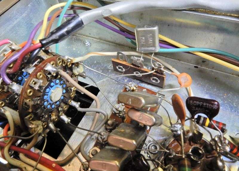
Find the white/brown wire from V1 pin 2 to the mode selector. Cut the wire at the selector lug. Strip the end of the wire. The outermost of the six crystals around the mode selector is stamped "E". Find and remove the bare wire from this crystal to the mode selector. Solder the stripped end of the white/brown wire to the hot side of crystal "E".
Mk3hotwire_X1after
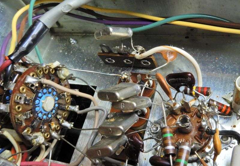
Find the gray wire from V1 pin 7 to the mode selector.
Mk3hotwire_X6B4
Cut the gray wire at the selector, strip the free end. Find the bare wire from the crystal stamped "F" and remove the bare wire. Solder the free end of the gray wire to the hot side lug of this crystal.
** Some radios have a white/gray striped wire, not a solid gray wire. **
Mk3hotwire_X6after
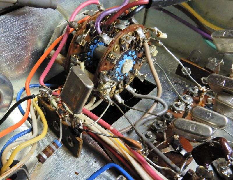
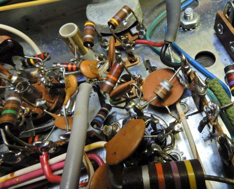
Find C6, a 470pf disc cap attached to pin 3 of V1. Find the white, or white/brown stripe wire on the other end of C6, follow it to the mode selector. Cut the wire at the selector.
M3hotwire_wire2C6
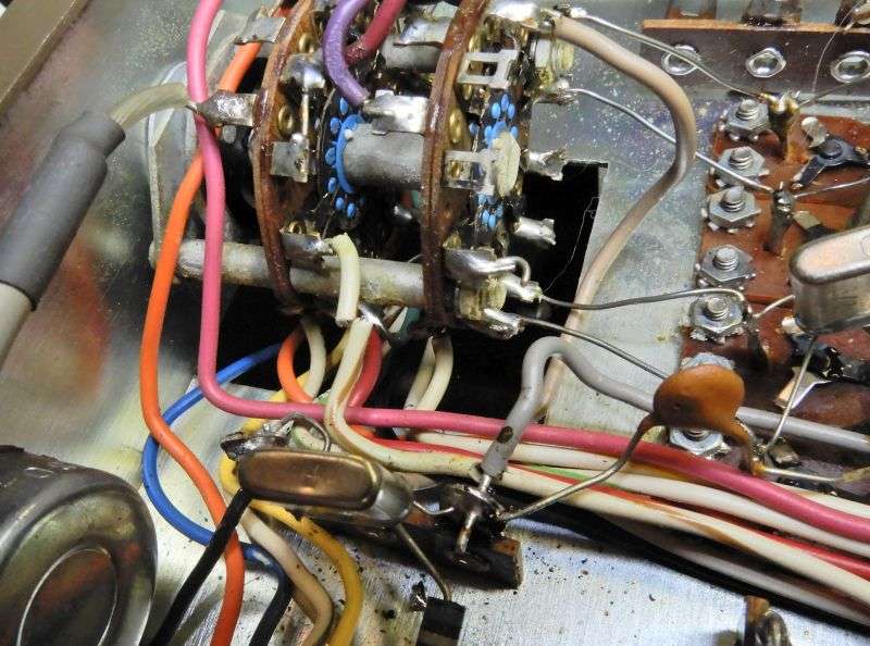
Find the shielded wire with the red and black wires.
M3hotwire_C10
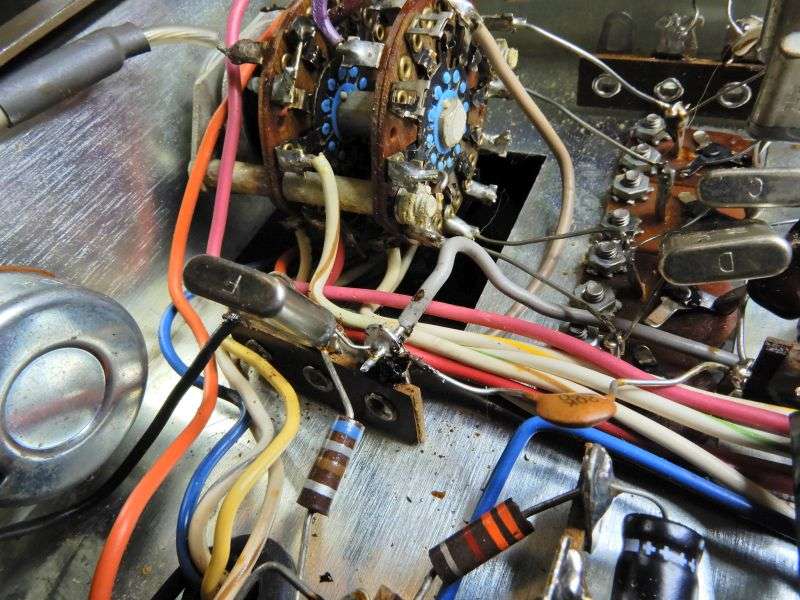
Remove this wire at both ends. Note the tiny ceramic capacitor soldered to the black wire. This is C10.
Solder the end of the white, or white/brown wire to the lug at C10 where the black wire was removed.
M3hotwire_C10_after
Remove the gray shielded wire that leads from pin 6 of V7 (12AX7) to the mode selector. Don't need this wire any more. It's the only shielded gray single-conductor wire on the mode selector. Shouldn't need a picture for that.
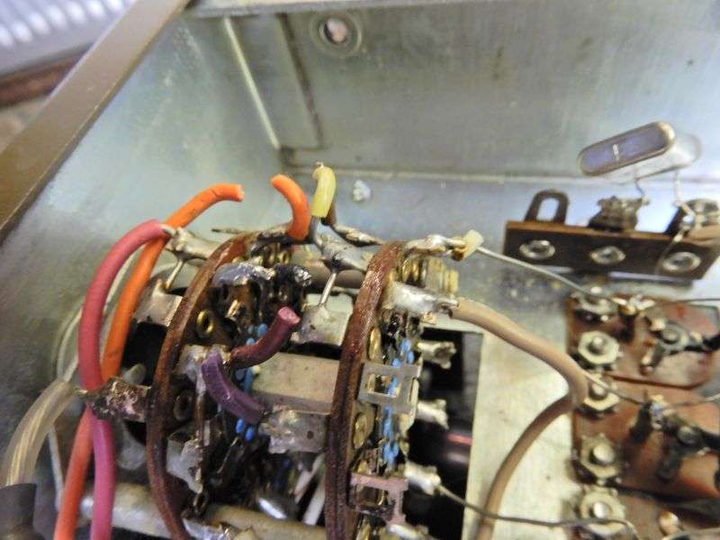
Next we tackle a bundle of wires that lead from the mode selector around the side and rear of the chassis.
In most radios they are yellow, brown, green and violet. The brown might be a white with brown stripe in some radios.
M3hotwire_four_wires
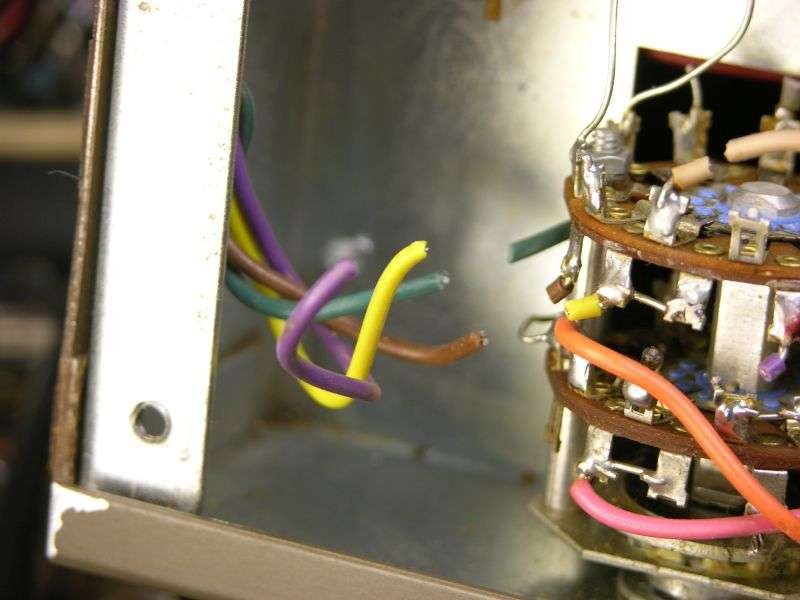
As seen, clip all four of these at the selector.
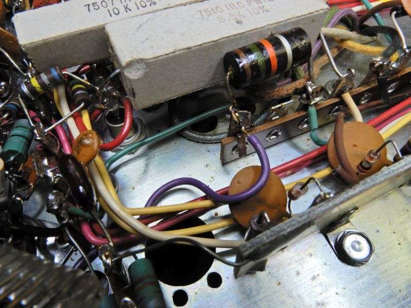
Follow the brown wire to the other end. This will be a 15k 2-Watt resistor R23. Lose the brown wire altogether. This view is from the rear of the transmitter's underside. Makes this brown wire at the left end of R23 easier to see.
M3hotwire_R23_cut_brown
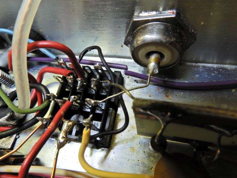
Follow the violet wire along the rear of the chassis and cut it where the coax socket meets the relay socket.
M3hotwire_Cut_violet
The violet wire leading * back to the mode selector * may be removed, along with the brown wire.
Strip the end of the violet wire that leads to the final tube. Route it to reach the end of R53 where the brown wire was just removed.
M3hotwire_solder_Violet_cut_green
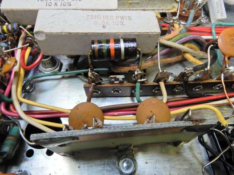
The green wire at the other end of R53 gets cut and the green wire removed.
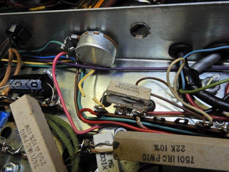
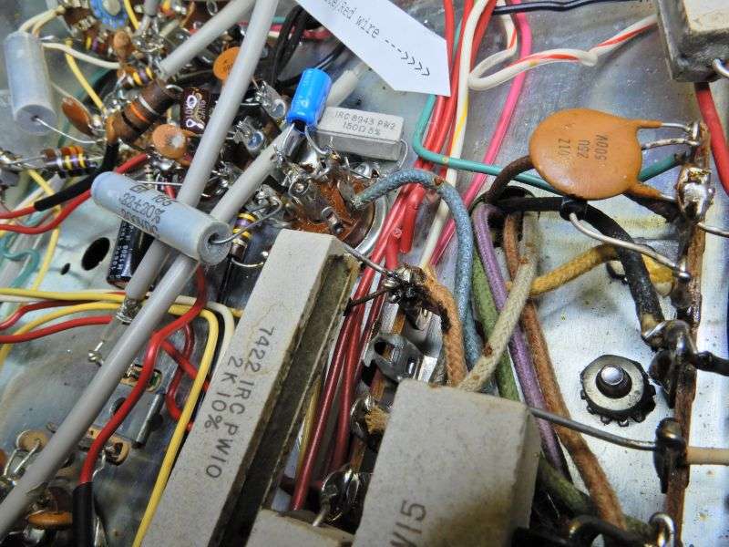
The yellow wire leads to R52, a 1500 ohm 5-Watt wirewound resistor along the rear of the chassis. Cut the yellow wire there and remove it.
M3hotwire_R52_cut_yellow
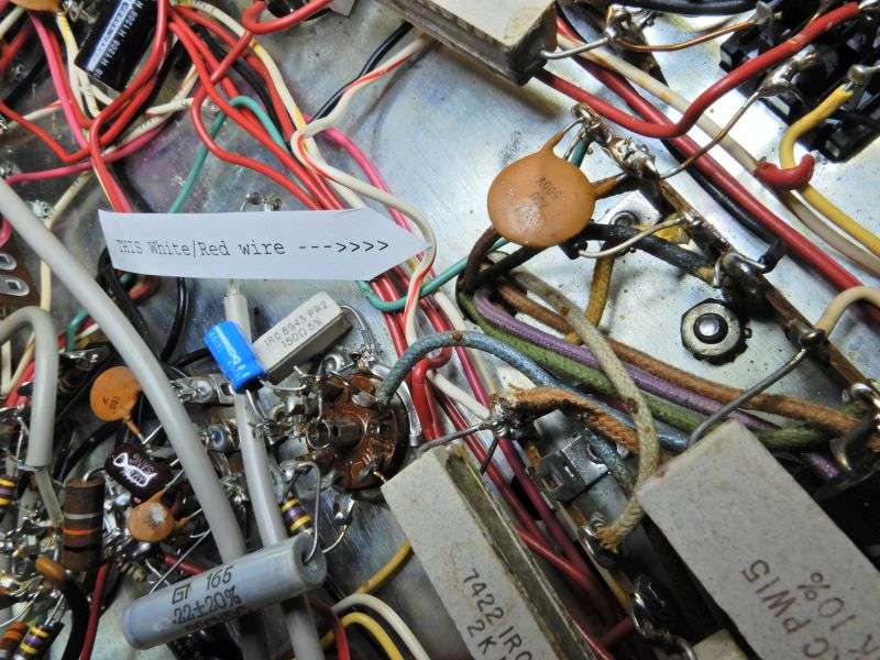
On the other end of R52 is a white/red wire that leads to the mode selector.
M3hotwire_R52_white_red
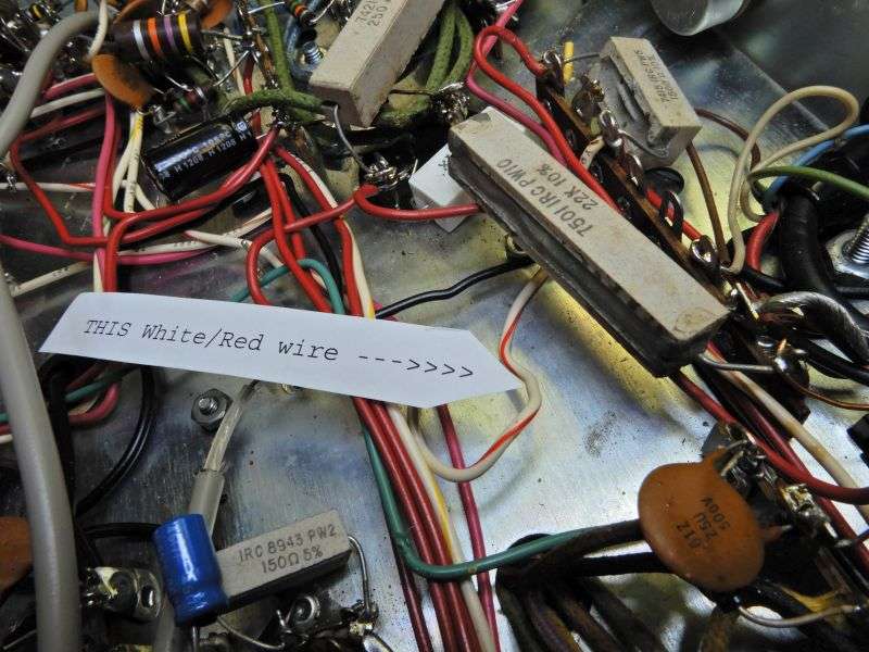
Follow it to the mode selector. Cut it there, and pull out its full length.
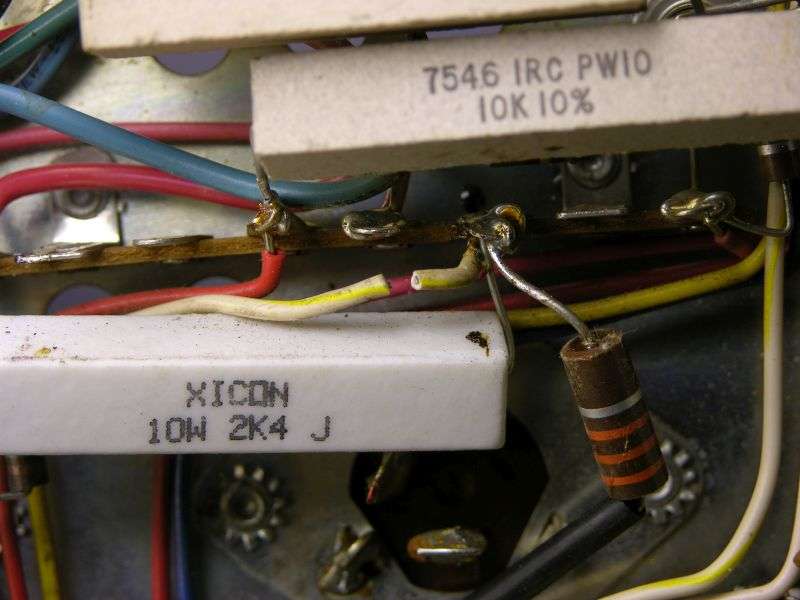
R49 is a 2k (usually) 10-Watt resistor with its inboard end right next to the modulator tube 6BQ5 socket. Cut the red wire from this lug, cut the other end of the red wire at the mode selector and remove it.
M3hotwire_R49_cut_red
You'll probably want to suck the solder out of this lug, and extract the cutoff end of the red wire. The free end of the white/red wire in the previous step gets the end stripped and soldered the end of R49 where the red wire was removed.
M3hotwire_R49_white_red
Coming out of the modulation transformer you'll find a black wire. It's soldered to a lug with a black plastic hookup wire.
M3hotwire_Black_wire_B4
Follow this wire and cut it long enough (about six inches) to comfortably reach the outboard end of R49
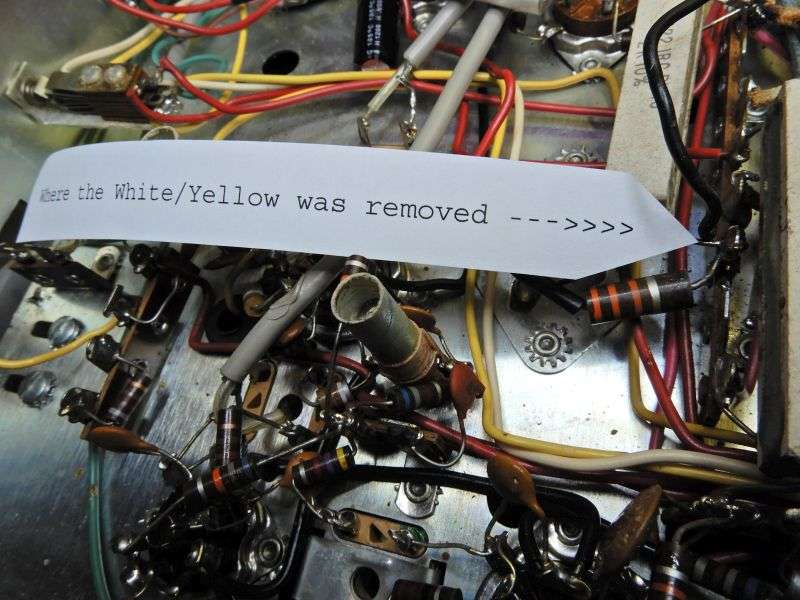
At the OTHER (outboard) end of R49 is a white/yellow wire and a 33k (three orange bands) 1-Watt resistor. The white/yellow wire gets removed from the radio altogether.
M3hotwire_R49_cut_white_yel
Strip, solder the end of the black wire to the outboard end of R49, where the white/yellow was removed.
M3hotwire_R49_black_wire
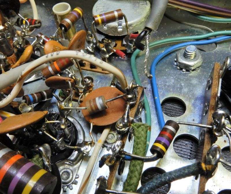
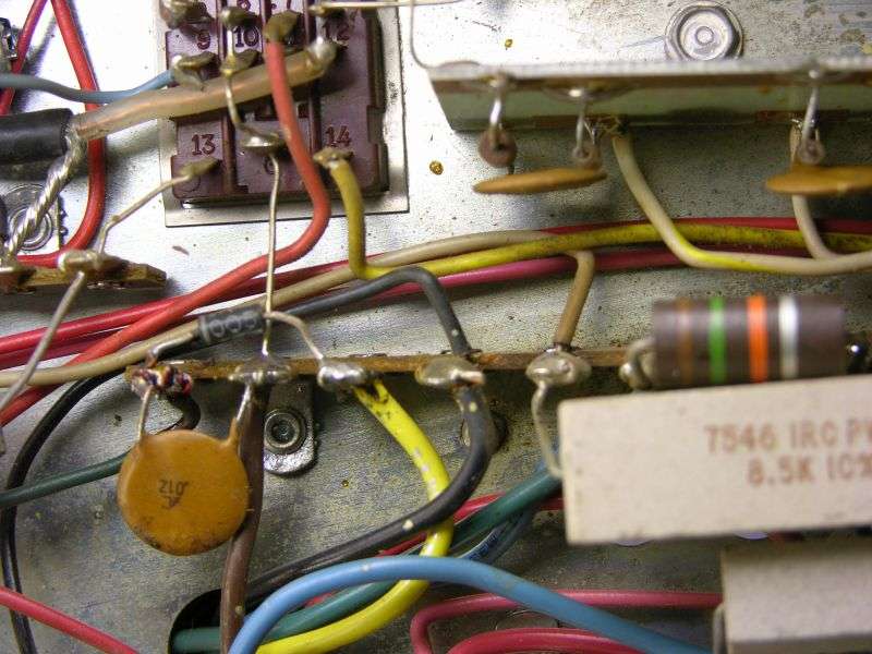
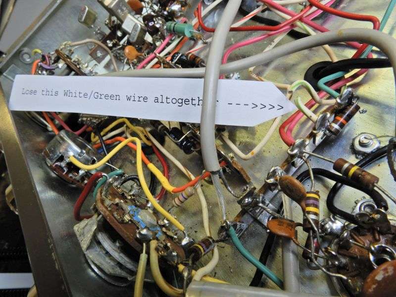
Find R53, a 10k or maybe 15k 1/2-Watt resistor mounted to the tie strip closest to V7, the 12AX7 tube. The rear-most end of R53 has a green wire on it. Leave the green wire alone. At the front-most end of R53 is a white/green wire. Clip this wire at both ends and remove it altogether.
M3hotwire_R53_lose_whi_grn
On the mode selector's front section is an orange wire that leads to the meter selector. Cut it at the mode selector. Pull it out of the bundle along the front panel.
M3hotwire_cut_orange
**** 20-image limit was reached here. Continued next post ***
*** Big whups department ***. Turns out that Xenforo only allows 20 images per post. This story has 24.. It will be whacked off at 20 pics and continued in the next post.
Dern!
The inevitable breakdown hazard of the mode selector in a Browning SSB transmitter is an expensive PITN.
Replacing the selector involves a lot of wires and a tight space to get them all moved from the old selector to a new one.
But why? The SSB performance of the Browning receivers is marginal at best. This makes the value of the transmit side seem small.
AM is what made Browning famous, not sideband.
Hot wiring the transmitter for AM only is a lot cheaper than replacing the selector. Probably less work all in all.
This example procedure is only accurate for the later version of the Mark 3 SSB transmitter. Easy to tell, it has a very-short 1/4-inch shaft trimpot sticking up out of the chassis deck next to the final tube. Earlier production does not include ALC for sideband transmit, and the internal wiring details won't be exactly the same.
Whether or when we'll have a detailed version for the 'old' version of the Mark 3 SSB transmitter is anybody's guess.
The usual disclaimers apply. The shop's original text file we use for this is written in shorthand, more or less. Probably wouldn't be clear enough to just pass around by itself. Even though that file has been "proofread" by using it to repeat this procedure, errors will still occur. The file you see here won't be totally debugged until we use it to perform the selector bypass and find no errors. Haven't done that yet.
The pictures in this file came from two different transmitters. The clearest example of some steps was in the first one, and some were in the second.
Soooooo. Repeat at your own risk.
Remember. If you break it you still have the pieces.
The first circuit of the mode selector to get bypassed will be the carrier-oscillator half of V1, 12AX7.
Mk3hotwire_X1B4
Find the white/brown wire from V1 pin 2 to the mode selector. Cut the wire at the selector lug. Strip the end of the wire. The outermost of the six crystals around the mode selector is stamped "E". Find and remove the bare wire from this crystal to the mode selector. Solder the stripped end of the white/brown wire to the hot side of crystal "E".
Mk3hotwire_X1after
Find the gray wire from V1 pin 7 to the mode selector.
Mk3hotwire_X6B4
Cut the gray wire at the selector, strip the free end. Find the bare wire from the crystal stamped "F" and remove the bare wire. Solder the free end of the gray wire to the hot side lug of this crystal.
** Some radios have a white/gray striped wire, not a solid gray wire. **
Mk3hotwire_X6after
Find C6, a 470pf disc cap attached to pin 3 of V1. Find the white, or white/brown stripe wire on the other end of C6, follow it to the mode selector. Cut the wire at the selector.
M3hotwire_wire2C6
Find the shielded wire with the red and black wires.
M3hotwire_C10
Remove this wire at both ends. Note the tiny ceramic capacitor soldered to the black wire. This is C10.
Solder the end of the white, or white/brown wire to the lug at C10 where the black wire was removed.
M3hotwire_C10_after
Remove the gray shielded wire that leads from pin 6 of V7 (12AX7) to the mode selector. Don't need this wire any more. It's the only shielded gray single-conductor wire on the mode selector. Shouldn't need a picture for that.
Next we tackle a bundle of wires that lead from the mode selector around the side and rear of the chassis.
In most radios they are yellow, brown, green and violet. The brown might be a white with brown stripe in some radios.
M3hotwire_four_wires
As seen, clip all four of these at the selector.
Follow the brown wire to the other end. This will be a 15k 2-Watt resistor R23. Lose the brown wire altogether. This view is from the rear of the transmitter's underside. Makes this brown wire at the left end of R23 easier to see.
M3hotwire_R23_cut_brown
Follow the violet wire along the rear of the chassis and cut it where the coax socket meets the relay socket.
M3hotwire_Cut_violet
The violet wire leading * back to the mode selector * may be removed, along with the brown wire.
Strip the end of the violet wire that leads to the final tube. Route it to reach the end of R53 where the brown wire was just removed.
M3hotwire_solder_Violet_cut_green
The green wire at the other end of R53 gets cut and the green wire removed.
The yellow wire leads to R52, a 1500 ohm 5-Watt wirewound resistor along the rear of the chassis. Cut the yellow wire there and remove it.
M3hotwire_R52_cut_yellow
On the other end of R52 is a white/red wire that leads to the mode selector.
M3hotwire_R52_white_red
Follow it to the mode selector. Cut it there, and pull out its full length.
R49 is a 2k (usually) 10-Watt resistor with its inboard end right next to the modulator tube 6BQ5 socket. Cut the red wire from this lug, cut the other end of the red wire at the mode selector and remove it.
M3hotwire_R49_cut_red
You'll probably want to suck the solder out of this lug, and extract the cutoff end of the red wire. The free end of the white/red wire in the previous step gets the end stripped and soldered the end of R49 where the red wire was removed.
M3hotwire_R49_white_red
Coming out of the modulation transformer you'll find a black wire. It's soldered to a lug with a black plastic hookup wire.
M3hotwire_Black_wire_B4
Follow this wire and cut it long enough (about six inches) to comfortably reach the outboard end of R49
At the OTHER (outboard) end of R49 is a white/yellow wire and a 33k (three orange bands) 1-Watt resistor. The white/yellow wire gets removed from the radio altogether.
M3hotwire_R49_cut_white_yel
Strip, solder the end of the black wire to the outboard end of R49, where the white/yellow was removed.
M3hotwire_R49_black_wire
Find R53, a 10k or maybe 15k 1/2-Watt resistor mounted to the tie strip closest to V7, the 12AX7 tube. The rear-most end of R53 has a green wire on it. Leave the green wire alone. At the front-most end of R53 is a white/green wire. Clip this wire at both ends and remove it altogether.
M3hotwire_R53_lose_whi_grn
On the mode selector's front section is an orange wire that leads to the meter selector. Cut it at the mode selector. Pull it out of the bundle along the front panel.
M3hotwire_cut_orange
**** 20-image limit was reached here. Continued next post ***
