
Here is a fault we have seen more than once in a Browning Mark 4A transmitter's PLL section. This is the part of the transmitter that Browning upgraded to transform the totally-unlucky Mark 4 into the useable Mark 4A. On the rear-inside edge of the PLL circuit board is a quarter-Watt resistor that routinely gets overheated. No markings can be seen in the boards's screen print, but it's R729. In the schematic it is seen to feed from the regulated 8 Volt supply to pin 1 of the MC145106 PLL chip. Seems like we only see this in transmitters that have had extra channel coverage added to them.
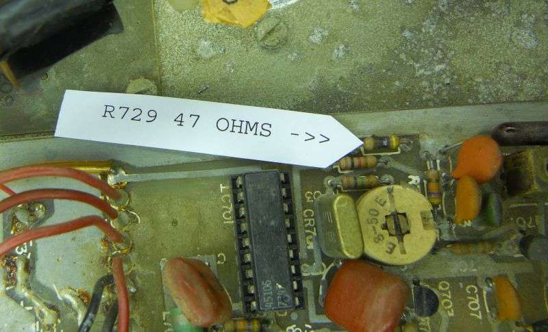
The fix is impossibly mundane. A new 47-ohm quarter-Watt resistor.
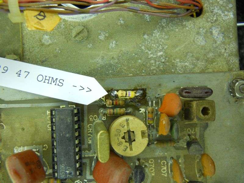
I'll guess that the extra-channel installation got a little sloppy and shorted the 8 Volts to ground only for a short moment. Just long enough to burn the paint off of R729. Couldn't find any other explanation.
Wacky part is that the burned resistor checked perfectly okay and the transmitter did, too. Apparently the resistance element inside the resistor is a lot tougher than the painted-on color bands. There is no component-placement diagram for this circuit board, so if you find this fault, this will save you the time identifying it.
73
The fix is impossibly mundane. A new 47-ohm quarter-Watt resistor.
I'll guess that the extra-channel installation got a little sloppy and shorted the 8 Volts to ground only for a short moment. Just long enough to burn the paint off of R729. Couldn't find any other explanation.
Wacky part is that the burned resistor checked perfectly okay and the transmitter did, too. Apparently the resistance element inside the resistor is a lot tougher than the painted-on color bands. There is no component-placement diagram for this circuit board, so if you find this fault, this will save you the time identifying it.
73
