• You can now help support WorldwideDX when you shop on Amazon at no additional cost to you! Simply follow this Shop on Amazon link first and a portion of any purchase is sent to WorldwideDX to help with site costs.

Carbon resistor help

IDIeselman

Active Member
Oct 20, 2010
260
38
38
53
Lake Michigan
20130120_135732.jpg
Well, I loaned out one of my RF linear K500's, 1+3 6LQ6's. Returned with the..something went snap and it's not working right:eek: 
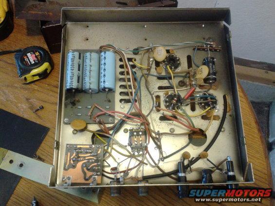
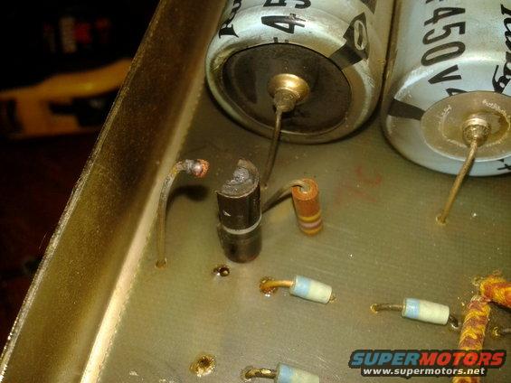
It appears it has blown a Carbon resistor of which I can not find a replacement or value for, all the charts say imput error too high of value. it appears to be 1-brown 2-black 3-gray 4-silver. Can anyone recommend a replacement or an outlet for a NOS resistor of the same values?

Thanks
Tim
 

At first glance it appears to be a voltage equalizing resistor in the hi-voltage power supply.
If I remember right those were usually on the order of 1/2 meg. (470k)
If that is what it is then you must use the same value as the other resistors on the board that are being used for that purpose.
That is so that they will divide the voltage equally amongst themselves.
Maybe you could reply with more information about the make/model of the unit and then this information can be gleaned from a schematic on CB Tricks.
 
This is a twin to the victim. all other resistors are different, possibly someone has done this before and replaced it with one that was "near" the rest. If any other pics will help I can take/post them.

k500-002.jpg
 

I am trying to insert a bitmap image that is stored on my computer....not sure how this is gonna work.
From looking at the schematic since my last post....( I found reference to the possibility that this is essentially the same as a Firebird 500 and that was found to be available on CB Tricks I now realize that this is not one of the equalizing resistors.
It now appears that the resistor in question is a 1 meg ohm 1 watt resistor.
Any way if the bimap image does not show up when I post this I will make another attempt to show you the schematic that seems to prove my assumption about the value of this resistor.
 
I have just tried to send it as an attachment and it tells me that the image is too large so I reduced its size to a fraction of its original and it still tells me that it is too large.
I am sure there is another way to do this or I could learn how to make the availabe functions work for me.
Maybe someone can offer some advice.

Thanks in advance
Radiooman
 
Let's think about this for a second. The amp probably only has about 800 volts inside. Values like 1 meg ohm at 2 watts can't burn open from this little voltage the way this one has done. This does not appear to be a high value resistor in parallel with the HV. I suggest it's a low value current limiting resistor in series with the DC line. It appears to be in series between the diode output and the input to the cap bank so that the caps do not appear like a short when they are being charge on power up.

Now to the question of why this resistor would burn open like this. If the resistor is between the diodes and the caps, it is most likely one or more of the diodes has shorted and applied AC to the caps, looking like a short circuit. The second possibility is the blue electrolytic caps may have shorted or the diodes could have damaged them if they shorted. The third possibility is the tubes may be shorted but not as likely. I suspect the blown resistor is a 10 ohm 2 watt and does not need to be carbon in this application.
 
The photo in the first post looks like the resistor lead was stressed too much when mounted and broke apart from age right at the end from heating and cooling over time.
The other colorations are normal dirt and migrations from heat effects.
 
In any event, if it's a bleeder in parallel, it will still work but may be a safety hazard since the caps may not discharge. In that case it may be around 470K. If it's a current limiting resistor in series, the amp will not work without it and it will be around 10 ohms. The schematic would confirm everything or even seeing the layout of the traces under the board.
 
It looks almost certain that one side of this resistor is connected directly to the positive terminal of the end capacitor. Where the other side of this resistor connects determines its value. From the picture it appears this side connects to a trace on the outside edge of the PC board. It may also connect to the corner screw that is grounded on the PC board. If that is the case, my original thoughts are not correct, it is a bleeder and between 100k and 470K is typical here. The other case is this outside trace may connect to a wire that feeds the B+ voltage into the tops of the tubes through the plate choke. Than it is in series and would be around 10 ohms. You should be able to tell by taking a quick look at the traces on the back of the board.

PS: All the burnt carbon deposits in the area suggest the resistor was over stressed by too much current passing through it and was probably in series around 10 ohms. The other possibility has already been pointed out by another member. If this resistor were physically stressed, the end terminal may have lost connection and could produce the same result through arcing without passing too much current and could be in parallel around 470K.
 

dxChat
Help Users
  • No one is chatting at the moment.