• You can now help support WorldwideDX when you shop on Amazon at no additional cost to you! Simply follow this Shop on Amazon link first and a portion of any purchase is sent to WorldwideDX to help with site costs.

Choke placement for a sleeve dipole for HomerBB.

The DB

Sr. Member
Aug 14, 2011
2,033
1,604
193
St. Louis, MO
Answer in a different thread for the sake of courtesy.

I like the idea, and done.

Excellent explanation in a short time. Curiously, In all my doings and reading, this approach to choking a halfwave endfed 1/4^ below the feedpoint (high voltage point) was never presented to me except perhaps with the Astroplane being choked 1/4^ below the ring.
I was even encouraged to place a choke at the coax entry point of a vertical sleeved dipole, the bottom of the lower tube, similar to the GM. (I guess I wasn't looking closely enough.) Isn't this also a high voltage point? (My 80m doublet is choked at the shack entry point.)

The sleeved dipole, this antenna took some work on figuring out the proper choking method...

As I did before, lets start out with an example of a worse case scanerio...

sdc1.jpg


As we can see, large common mode currents. And choking at the bottom of the sleeve does not, in and of itself, fix the issue as we can see here with an 8000 ohm impedance choke.

sdc2.jpg


My first thought would be to put the choke at the feed point of the antenna inside the sleeve if possible (likely using ferrite beads around the feed line inside the sleeve, but as we can see below, that didn't work out that well either.

sdc3.jpg


What happened here is the choke actually worked as their is almost no current flow on the wire below said choke, however, mutual coupling with the wires representing the sleeve below the choke induced currents on the feed line/mast. Putting a second choke below the sleeve also does not prevent common mode currents in this case. This is how I would have choked such an antenna before today, and as we can see, it wouldn't have been very effective...

Anyway, moving on to what I did with the End Fed Half Wave antenna in the other thread. The choke is located near 1/4 wavelength below the voltage peak, or in this case, near 1/4 wavelength below the bottom of the sleeve.

sdc4.jpg


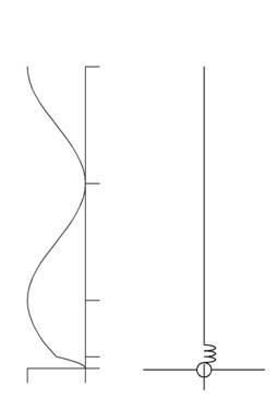
At first glance this appeared to work, however, as I played with mast lengths further this happened as a worst case scenario...

sdc5.jpg


As we can see, it isn't nearly as bad as above, in most cases isn't likely to cause to many problems, but their is enough currents present that I cannot guarantee that. This is with an 8000 ohm impedance choke as well. The choke is definitely trying to do its job, but some current is still getting through.

If you have this setup and are having problems, what do I suggest you do? Add another choke 1/4 wavelength below the choke above. When I model that it doesn't matter what I do with the feed line below, their are no noticeable currents flowing on it. Yes, I am saying that in a worst case scenario, you might want to use two chokes with this antenna design...


The DB
 
  • Like
Reactions: HomerBB

I don't have one up currently, but several are up in the area.
What intrigues me at this point is why the high voltage point on the GM 5/8 sleeved dipole is not producing CMC complaints from users like the A99 and similar EFHW antennas have.
OTOH, the neccessity to mount the GM at minimum height above other conducting materials may be a nod from the developers to the potential CMC issues of that antenna. Your thoughts...?
I will use the double choke feature in the future.
 
When it comes to the Gainmaster, I think you are seeing it backwards. In that case, they are not putting the choke at the voltage node, instead they are using the choke to force a voltage node to be where they want it to be.

One thing I have noticed with modeling, any antenna that has a voltage node at or near its base gets near the ground or other objects and the antenna suffers, both in performance and being detuned. My modeling, as well as other people's claims from actually trying it agrees with Sirio's recommendation for the Gainmaster of mounting it at least a half wavelength above the ground. These types of antennas tend to be far more sensitive to things being near the bottom of the vertical element than other antenna designs. The reason for this centers on where the voltage node is on these antennas.


The DB
 
And, yet, the voltage node is not near the bottom where the sleeve is terminated by the bottom? The question is whether the necessity of mounting the GM so far away is because of CMC being inadequately handled.
I have seen innumerable references to the GM being a 5/8^ dipole. If so, I fail to see why they need to induce a high voltage node anywhere, it should have it already, it's an antenna, after all. Is there a high voltage node at the bottom and top of the antenna, or the ends, as in all resonant dipoles, or does this one get a pass because so many folks like it, or it's a 5/8, or ...
And if it does behave typically, where are the CMC? I suspect in the customary places, coax, mast, shack, neighbors touch lamp, . . .
 
The GM is a center fed 5/8th dipole so the high voltage node is 1/16th wave length up from the choke.This might be why the GM choke is so effective + its a big choke. Might not be 100% effective but it is close.

I've made about a dozen copies of the GM on frequencies from 6m to 20m all have excellent cmc suppression .

Also I haven't found it to be" far more sensitive to things being near the bottom of the vertical element than other antenna designs". in fact its the opposite . My 20m versions choke is only 2 ft above a metal chainwire fence with no adverse affects Again I contribute that to it being 5/8th with the voltage node higher up.

Not sure what the 60 pf ( from memory)cap in the bottom of the top element is doing to the distrubution as there seems to be no element length corrections

DB didn't you model one awhile ago?

I have tried the GM dimensions choke on sleeved dipoles and it does work better than the standard 5 turn version most use . However it is as DB describes with some CMC evident.
 
  • Like
Reactions: HomerBB
Thanks!
That's what I thought the answer would be, ie the voltage node 1/16 up from the ends. I just am curious about the advice to separate it from the earth, or metal fences, etc, and how that may play into any CMC issues.
Not trying to be a hard head.
 
Homer.
you can't have a voltage node 1/16 wave from the ends

When you imagine or draw the current & voltage distribution of unloaded antennas.
Always start with a voltage maxima/current minima at the end or ends if its a dipole and work back towards the feedpoint.

1/4wave down from the ends you have current maxima & most radiation,

When you change electrical length of the antenna or change frequency on the same antenna the ends remain at a voltage maxima current minima even if you chop the antenna in half ,

Current maxima is only at the feedpoint of a resonant 1/2wave dipole 1/4wave from the ends.
on the gainmaster current maxima is 1/4wave from the ends or about 1/16wave the from feedpoint.
 
  • Like
Reactions: HomerBB and The DB
he GM is a center fed 5/8th dipole

Yes.

so the high voltage node is 1/16th wave length up from the choke.

I hate to be a downer but no.

I am curious why you would think this is the case. Do you think the feed point is what determines the voltage and current distribution? If so that is in error. On a center fed dipole the tips of the antenna are by definition voltage nodes. The two current nodes are a short distance from the center, one on either side of said center.

I also find it curious that you talk about a center fed 5/8 wavelength antenna, then post an example of an end fed 5/8 wavelength antenna? Here is a center fed 5/8 wavelength antenna current distribution. Where the currents go to 0 the voltage peaks and vice versa.

cf58.jpg


Not sure what the 60 pf ( from memory)cap in the bottom of the top element is doing to the distrubution as there seems to be no element length corrections

DB didn't you model one awhile ago?

I did successfully model the Gainmaster a while ago, I think Eddie has also succeeded in modeling the antenna since then as well, at least as far as its bandwidth is concerned. To explain what was happening I had to use smith charts, which honestly (and unfortunately) isn't commonly used or understood by many people in the hobby radio world. Here is a link to the thread, although me my modeling isn't until a few pages into said thread. The results using the smith chart can be found in this post. I don't remember the capacitance I used for the capacitor, I know it was lower than 60 pF. I took the type and length of coax used in the Gainmaster and used that to find the capacitance I used.

I can tell you that the results I got that resembled the actual Gainmaster antenna required any number of things to be accurate. One of them was the size of the capacitor, one was where the feed point was located, which was just off center, one was the overall length of the antenna, which as I recall might have been just over the 5/8 wavelength length, also the stub match wasn't set to go to a perfect match, so the default values the modeling software tried to use had to be modified as well. It really was a balancing act.

I haven't modeled a Gainmaster with a choke between the antenna and the feed line below. Perhaps I should. I'll see if I can't do it sometime today as I will have to dig up the models I haven't touched in over a year.


The DB
 
  • Like
Reactions: HomerBB
Did a model with a center fed 5/8 wavelength dipole with a choke and its worst case scenario for common mode currents below the choke.

cf58c.jpg


I want to point out again, this is a worse case scenario, namely 1/2 wavelength of feed line feeding the antenna. Their isn't a lot, compared to what is being radiated from the antenna, but their are still some common mode currents present. However, very few people will use a feed line of this length for this antenna. The 50 foot plus lengths people tend to use are more than twice this, so I looked for the near one wavelength point and got this...

cf58c2.jpg


As we can see, with the longer feed line, this one will be just under 40 feet in length, the magnitude of the common mode currents is noticeably less than above, the total current appears to be shared between the two lobes. If the feed line is long enough to have a third full lobe then this would happen again. Also, if you are really concerned about it then you can put a second choke near 1/4 wavelength below the antenna, that will fix the common mode currents issues once and for all. Here is what that looks like...

cf58c3.jpg


I guess what this and the above are showing us is a single choke does not always eliminate all common mode currents. The determining factor of how well a single choke works is the electrical length of the feed line between the choke and the far end of the feed line. In any case, if you happen to have one of these unlucky feed line lengths that you still have common mode currents problems that need to be resolved, a second choke near 1/4 wavelength down from the first choke will resolve the issue.

Their are two things I am noticing than I have not considered before this point:

The longer the electrical length of the feed line between your radio setup and your antenna, the weaker the common mode current peaks tend to be. It appears that the power for the common mode currents seems to be split between the various current peaks on this feed line.

A longer choke of the same impedance seems to do a better job at minimizing common mode currents.


The DB
 
  • Like
Reactions: HomerBB
Homer.
you can't have a voltage node 1/16 wave from the ends

When you imagine or draw the current & voltage distribution of unloaded antennas.
Always start with a voltage maxima/current minima at the end or ends if its a dipole and work back towards the feedpoint.

1/4wave down from the ends you have current maxima & most radiation,

When you change electrical length of the antenna or change frequency on the same antenna the ends remain at a voltage maxima current minima even if you chop the antenna in half ,

Current maxima is only at the feedpoint of a resonant 1/2wave dipole 1/4wave from the ends.
on the gainmaster current maxima is 1/4wave from the ends or about 1/16wave the from feedpoint.
ok. I should have used maxima instead of node to even begin to track correctly on this thread. But, then again, you may not have given such a clarifying reply. Thanks.
 
Great, DB!
So, one more thing.
What does the CMC look like on the dipole (and/or EFHW) with no choke. Or, is that done in the first model on the thread?
 
The first model in this thread was the sleeve dipole you requested that created this thread. That being said, the one I posted first in the other thread was an end fed half wavelength antenna with a worst case scenario for CMC. I'll re-post the image here.

nochoke.jpg


And the image that had the 8000 ohm choke in a bad location, namely right at the feed point, is this one.

fpchoke.jpg


Not much of a difference between them is there...


The DB
 
  • Like
Reactions: HomerBB
OK thanks for the correction Guys very informative. The mystery remains though Why in real life testing is the GM so good at suppressing CMC at any feed length ? Found the cap value 8.64 pf for 10-11m.
 
Last edited:

dxChat
Help Users
  • No one is chatting at the moment.
  • dxBot:
    Tucker442 has left the room.
  • @ BJ radionut:
    LIVE 10:00 AM EST :cool:
  • @ Charles Edwards:
    I'm looking for factory settings 1 through 59 for a AT 5555 n2 or AT500 M2 I only wrote down half the values feel like a idiot I need help will be appreciated