Is there any certain length for coax running to a wire dipole? I am going to mount the dipole in an inverted V from a 20' painters pole. I have tried the dipole about 8-10' feet off the ground and would use a couple of 18 footers with a barrel connection and actually had decent results. But I want to see what it will do higher off the ground. What coax type would be best?

You are using an out of date browser. It may not display this or other websites correctly.
You should upgrade or use an alternative browser.
You should upgrade or use an alternative browser.
-
You can now help support WorldwideDX when you shop on Amazon at no additional cost to you! Simply follow this Shop on Amazon link first and a portion of any purchase is sent to WorldwideDX to help with site costs.
-
A Winner has been chosen for the 2026 July 4th Retevis RA89R Giveaway! Click Here to see who won!
Coax length for wire dipole
- Thread starter codeman
- Start date
of the 3 dipoles i homebrewed i used just regular tv flat wire in to a tuner with wire connections,,,but that is just me experimenting,, it worked fine made a lot of contacts,,, but there are so many different ways to do dipoles,,, seen rg 58, rg8 rg 8x used then there are 300 400 ohm flat wires used with tuners or baluns,,, i think you just have to chose and experiment what works in your application
Is there any certain length for coax running to a wire dipole?
Is it me or has essentially the same question come up a lot lately?
The one and only correct length is the length needed to get it from the antenna to the radio, with a little extra for wiggle room. If changing the length changes the apparent tune of the antenna then you have an antenna problem that needs to be dealt with.
The DB
Best to get a 1:1 matching balun and add wire cut to resonant freq. Then use what reaches from the feedpoint to your radio as far as coax goes!! Leave some slack for service if needed. JMHO.
I shun superstition, especially the CB myth type and would I have NOT seen a definite performance difference (on an antenna which was showing an SWR of 1.0:1, reactance of X=0/1 & Resistance of 51Ω) when cutting down from a length of RG-213 coax cut to an odd multiple of a 1/4 wave (x VF) to an odd or even multiple of a full wave, (x VF) - I'd be inclined to agree with your theoretically correct position.Is it me or has essentially the same question come up a lot lately?
The one and only correct length is the length needed to get it from the antenna to the radio, with a little extra for wiggle room. If changing the length changes the apparent tune of the antenna then you have an antenna problem that needs to be dealt with.
The DB
I now always make certain I plan my coax so it is a multiple of a full wave x VF, even though many believe it to be no more than superstition or myth, only because I have attained performance improvements from doing so, even on "correctly tuned" antennas. Someday I hope to fully understand why.
")
Needle Bender I have researched that odd multiples of coax length for installs, always heard or read it should be 1/2 wl of course velocity factor figured in.
Same with using ladderline, there are "certain" lengths to avoid when using an all band doublet type antenna.
I have not "seen" any difference with any length of coax once I have the antenna tuned using the analyzer, I just stick on any old length of coax and start making contacts.
I have an 75/40 meter fan dipole up at 45', I talk to BJ and Fire runner in the mornings on 75 meters, BJ being in Indiana and Fire Runner being in California.
I am using 75ohm RG6 quad as coax and my impedance is 50 ohms X=0 and that old wire sure hums when I turn that 3-1000Z loose. I did not measure it, just put the connectors on the end and started using it.
For tuning an antenna YES a 1/2 wl of coax is great. After it is tuned then whatever length is needed has worked for me.
I really want to see a difference in connecting a certain length of coax to an antenna and it improve the rx and tx gain just by using a tape measure to measure and cut transmission line.
Not saying you have not seen this happen, I just wished I could see it happen also as my weak ass signal can use all the help it can get")
Same with using ladderline, there are "certain" lengths to avoid when using an all band doublet type antenna.
I have not "seen" any difference with any length of coax once I have the antenna tuned using the analyzer, I just stick on any old length of coax and start making contacts.
I have an 75/40 meter fan dipole up at 45', I talk to BJ and Fire runner in the mornings on 75 meters, BJ being in Indiana and Fire Runner being in California.
I am using 75ohm RG6 quad as coax and my impedance is 50 ohms X=0 and that old wire sure hums when I turn that 3-1000Z loose. I did not measure it, just put the connectors on the end and started using it.
For tuning an antenna YES a 1/2 wl of coax is great. After it is tuned then whatever length is needed has worked for me.
I really want to see a difference in connecting a certain length of coax to an antenna and it improve the rx and tx gain just by using a tape measure to measure and cut transmission line.
Not saying you have not seen this happen, I just wished I could see it happen also as my weak ass signal can use all the help it can get
...I now always make certain I plan my coax so it is a multiple of a full wave x VF... I have attained performance improvements from doing so, even on "correctly tuned" antennas. Someday I hope to fully understand why.
think about the voltage to current ratio as it travels along the coax (a sine wave is formed),
they are 90 degrees out of phase along the sine wave. when one is max, the other is min.
so,.... with an e wl (or 1/2 e wl multiples) of coax being used, the V and I are the same at the load as at the xmitter, where V is max and I is min (... and the impedance is.........?
") )
)... there are "certain" lengths to avoid when using an all band doublet type antenna.
I have not "seen" any difference with any length of coax once I have the antenna tuned using the analyzer, I just stick on any old length of coax and start making contacts....
I really want to see a difference in connecting a certain length of coax to an antenna... my weak ass signal can use all the help it can get
go here https://www.google.com/url?sa=t&rct=j&q=&esrc=s&source=web&cd=1&cad=rja&uact=8&ved=0ahUKEwjVx6zz3KrKAhUK5mMKHf8ODZYQFggeMAA&url=https://en.wikipedia.org/wiki/Lecher_lines&usg=AFQjCNFCmhK51T6H-l1s_abx4pmG0Ae6TQ
this is useful for tuning stubs vs lumped LC circuits primarily at the higher freqs.
think about the voltage to current ratio as it travels along the coax (a sine wave is formed),
they are 90 degrees out of phase along the sine wave. when one is max, the other is min.
so,.... with an e wl (or 1/2 e wl multiples) of coax being used, the V and I are the same at the load as at the xmitter, where V is max and I is min (... and the impedance is.........?
I understand the principal of the mathematics in above quote, I have also read Walt Maxwells "Reflections". All I am saying is I have yet to see ANY length of transmission line increase RX or TX,
Let me say in my own experience I have found that if you need to have a certain length of coax to make your readings at the radio good, then you have a mismatch or other issues. You should be able to run from point A to B and be done. If the load at the end of the coax is 50ohms then the readings at the radio should be the same as that at the load connected directly to your antenna analyzer. If it's not, then either you have a coax issue or your antenna analyzer is out of calibration.
It helps to place a 50ohm dummy load directly attached to your antenna analyzer and check what it reads. This will give you a good base line as to reference to. JMHO.
It helps to place a 50ohm dummy load directly attached to your antenna analyzer and check what it reads. This will give you a good base line as to reference to. JMHO.
I shun superstition, especially the CB myth type and would I have NOT seen a definite performance difference (on an antenna which was showing an SWR of 1.0:1, reactance of X=0/1 & Resistance of 51Ω) when cutting down from a length of RG-213 coax cut to an odd multiple of a 1/4 wave (x VF) to an odd or even multiple of a full wave, (x VF) - I'd be inclined to agree with your theoretically correct position.
I now always make certain I plan my coax so it is a multiple of a full wave x VF, even though many believe it to be no more than superstition or myth, only because I have attained performance improvements from doing so, even on "correctly tuned" antennas. Someday I hope to fully understand why.
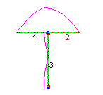
Your coax was forming part of the antenna and even radiating a signal if you did not put a RF choke at the antenna feedpoint so by choosing specific lengths you're effectively tuning the antenna system. This is even true in a balanced antenna like a dipole because the current that is flowing on the inside of the braid will split between the dipole element and the outside of the braid when it gets to the dipole leg connected to it, the amount going down the outside of the braid being determined by the impedance it sees in the dipole leg and the braid - Kirchoffs Current Law. That is why you use a RF choke so it sees the outside of the braid as high impedance and forces ideally all, but in practice most, of the RF current into the dipole leg instead. This is even more of a case in something like a vertical antenna where if there is no groundplane or a poor one it'll see the outer braid of the coax as the path of least resistance by a massive amount.
Flow of RF current in a Dipole with no choke:
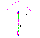
Dipole with a decent resistive choke:
Finally below, Dipole with a reactive (air wound) choke if you get it wrong and the inductive capacitance cancels out the reactive capacitance of the coax. Note how little flows in the dipole leg 2 which is connected to the braid. That is because the outer braid of the coax now forms a path of almost no resistance so the current flows there instead
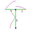
(images courtesy of Steve G3TXQ)
Last edited:
Thanks for all the answers, honestly a lot of the info is over my head. I have a wire dipole i bought that came with a balun. So I will buy 50-70 feet of RG-8X and see how it performs.
Thanks for all the answers, honestly a lot of the info is over my head. I have a wire dipole i bought that came with a balun. So I will buy 50-70 feet of RG-8X and see how it performs.
It'll work great for DX - horizontal dipoles don't do so well for local due to the whole issue of vertical and horizontal polarised antennas and the losses when one tries to talk to the other. Try to keep it at least 16ft high.
go here https://www.google.com/url?sa=t&rct=j&q=&esrc=s&source=web&cd=1&cad=rja&uact=8&ved=0ahUKEwjVx6zz3KrKAhUK5mMKHf8ODZYQFggeMAA&url=https://en.wikipedia.org/wiki/Lecher_lines&usg=AFQjCNFCmhK51T6H-l1s_abx4pmG0Ae6TQ
this is useful for tuning stubs vs lumped LC circuits primarily at the higher freqs.
I nominate this post by Road Squawker as one of this years best.
Well put.Basically we want our antennas to get the RF the same as it would if it were attached to the coax connector on the back of the radio.
Although, I have wondered if any difference in either efficiency or TOA would be measured if, depending on the phase of the feed point/matching network, the phase of the RF in the coax were matched to it..?

Regarding feeding a dipole, I prefer to use a length of odd 1/2 wave multiples using the VF of the CASING, for there to be a 1/2 wave in there somewhere to raise the impedance to help make it less interesting to potential RFI.
Math and formulas are wonderful but just get some wire, a balun and coax and have at it as 222 said above.Best to get a 1:1 matching balun and add wire cut to resonant freq. Then use what reaches from the feedpoint to your radio as far as coax goes!! Leave some slack for service if needed. JMHO.
dxChat
- No one is chatting at the moment.