As popular CB radios become older they get senile.
In a way. Aluminum electrolytic capacitors have a finite life span. And a radio with dozens of them inside can develop a whole spectrum of quirks and outright failures as they fail.
Problem is, the age alone is not the only factor. Mileage counts. A new-in-the-box 1980 radio probably works okay. The same model that spent 20 years in a truck cab, on the dash baking in the sun every summer will have failed parts sooner than a radio used only indoors. Tube-type radios generage a lot of internal heat. They tend to wear out electrolytic caps faster than most solid-state radios.
And the initial quality of the parts is a factor. There's just no good way to pin down how it will affect any one radio.
Bottom line, if the radio is 30 years old, you may only find one or two of those caps with a problem. At 40 years old, it's pretty likely. At 50 years old it's nearly guaranteed.
Odds. Probabilities. And if you want a 40 or 50 year-old radio to be dependable, you need to just bite the bullet and change all of the electrolytics in a radio that has any significant mileage on it. Too bad there's no odometer to base that judgement.
This radio is a Cobra 138XLR. A 40-channel sideband CB with the uPD858 PLL chip. This technology lasted about one year. The FCC figured out how easy it was to get channels that are not legal from it. The radio was made by Uniden, and the pc board inside it was sold with Cobra, President, Robyn RatShack and other names on the outside. By 1979, this design was replaced with new models that had channel selectors and PLL chips that were more locked-down from getting more than 40 channels.
It won't be 50 years old for a little while yet. But it's old enough to get the re-cap treatment.
I'm using a kit from Klondike Mike. There's a good chance I have all the caps it needs in my shop's stock, but the labor to pull them off the shelf make's Mike's package price look good in comparison. The kit shows up in a small zip bag. No, you don't need a pic of that. A list of what's inside is posted on the web. A small card with the URL is included with the parts. Fair warning, the PDF with the list inside is password protected. The password will be on the card with the URL packed in the bag. I won't show any pics of that, since this list is part of what you're buying along with the parts.
They're all packed into a single zip bag.
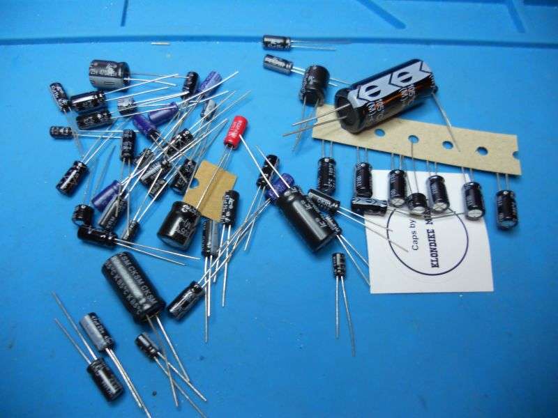
Disclaimer: Not every radio with this circuit board uses the same cap kit. Mike lists one for this radio, but I was impatient and used a kit already on hand marked for the Realistic TRC-457. Yes, same circuit board, but it's a base, not a mobile. Turns out there are other small differences. Ended up with unused parts. That's to be expected. Also ran out of another. Not Mike's fault. I had them in stock, so it wasn't an issue. But if you don't have that kind of inventory on hand, be sure to order the kit for the exact model you want to rehab. Lesson learned.
IIRC this kit contains 51 parts. The correct kit for the 138XLR probably contains a shorter list.
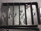
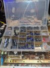
My preferred method is to mark a snack-size zip bag with the value of each part that appears twice or more on the list.
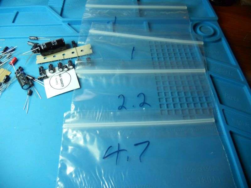
There are a few 'single's, with a capacitance value that shows up only once on the list. They get put together in one bag.
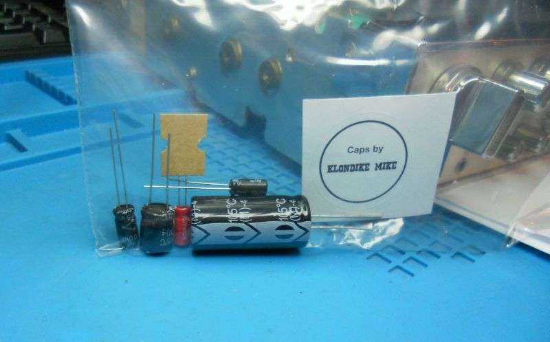
The intent is that as I remove a part from the circuit board and read the value off of it, the new one to replace it is marked on the bag where it's found. It can't hurt to eyeball the schematic callout printed next to the empty spot and check Mike's list. That list may or may not be exactly right for every production run. If you pull out a 1uf cap and Mike's list shows a different value for that callout number, use the one marked on the list. If you don't you'll run out of one value before you're done and have others left over.
Pay attention to the polarity marked on each part as you pull it out. Odds are the "+" on the circuit board will agree with the "-" marked on the cap. Now and again you'll find a misprint on the circuit board's screen-print legend. If the cap is marked opposite the polarity marked on the circuit board, believe *the part*, not the board's markings.
I do have one suggestion I need to pass along to Mike. He doesn't include tantalum capacitors, only the aluminum electrolytics. I'm okay with that, since tantalum caps don't have the lifetime clock ticking away like the aluminum 'lytics. Tantalums just last longer on average. But this radio has an almost-certain failure that has nothing to do with age. C179 is a 2.2uf 25-Volt tantalum. That 25-Volt rating is fine until you turn up the AM modulation. That puts peak voltages well in excess of 25 Volts across this part. Big surprise, it fails as an annoying short. Can be bad juju for the relay. It's made from unobtanium. We learned decades ago to replace C179 with a 35-Volt or higher cap any time we looked inside this family of radios. Since this is really a "must replace" part, I'll recommend he add a 2.2uf electrolytic to the list. Doesn't have to be a tantalum. For that matter, there are folks who will tell you to just leave it out. I don't. You decide.
Someone had already done it to this radio, but with a slightly-clumsy looking axial cap.
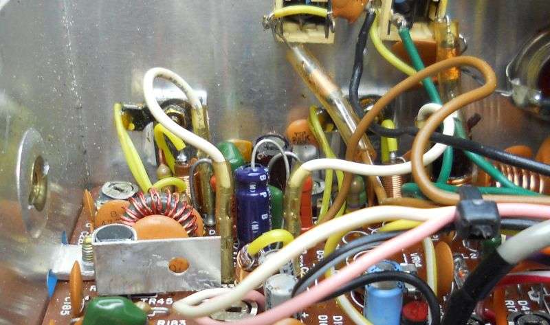
This is a large job that will probably take you more than just one continuous sitting. To keep track of what's been changed and what hasn't, we mark the top of every factory cap with a black Sharpie pen.
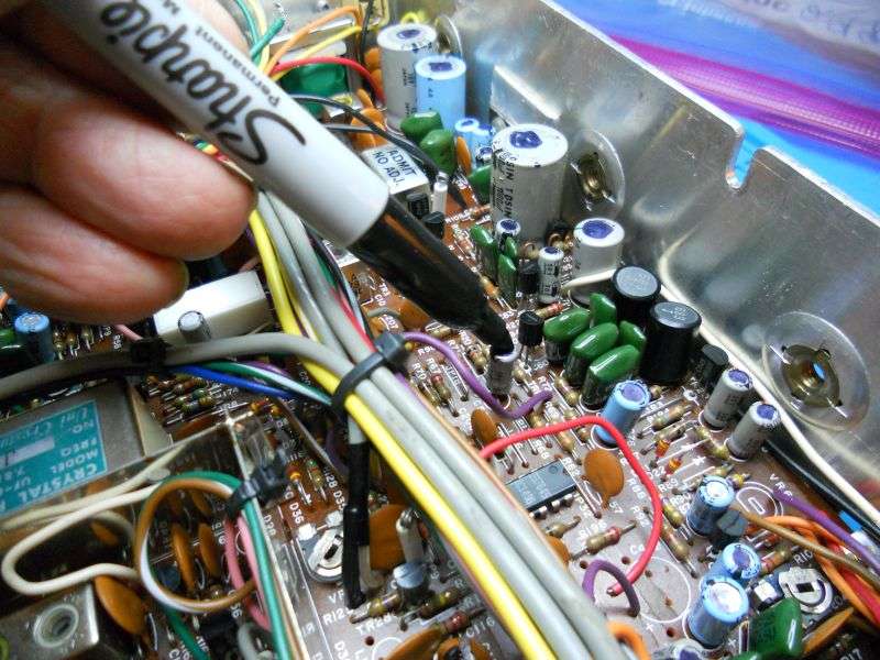
I adopted the habit of doing these re-cap jobs at home after my wife goes to bed. Don't need a full-blown service bench for this task. And it reduces interruptions. But it takes more than one evening to finish doing it this way. Marking the original parts prevents confusion about what's new and what's not.
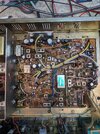
Some parts are obscured by the wiring harness. Cutting the zip ties will help gain access to some of the caps.
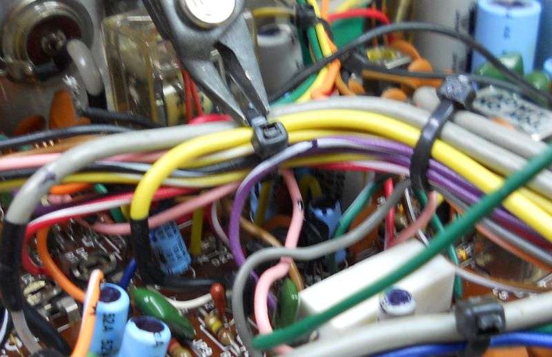
Can't mark 'em if you can't reach 'em.
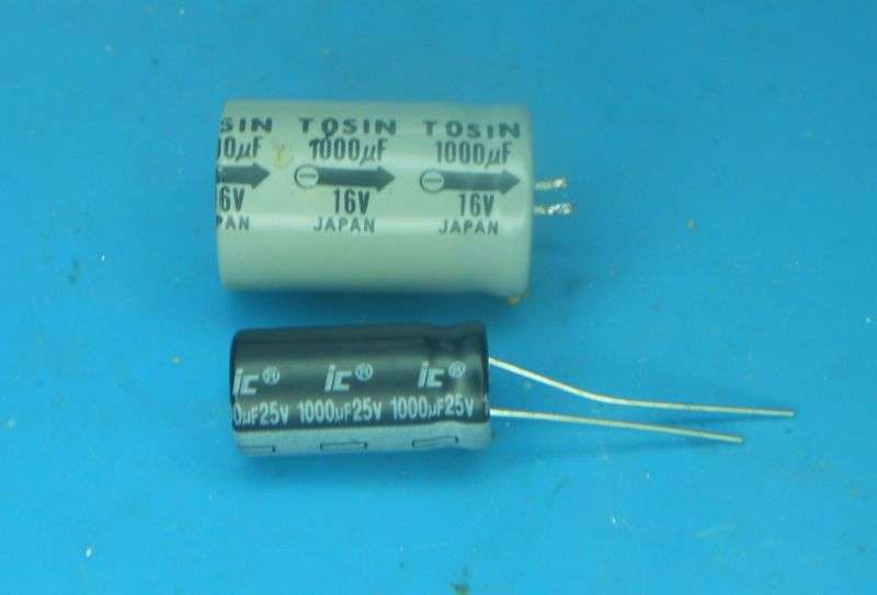
You'll see a size difference between new caps and 50 year-old equivalents. The tech has evolved over the decades. The largest capacitance values reveal the most shrinkage.
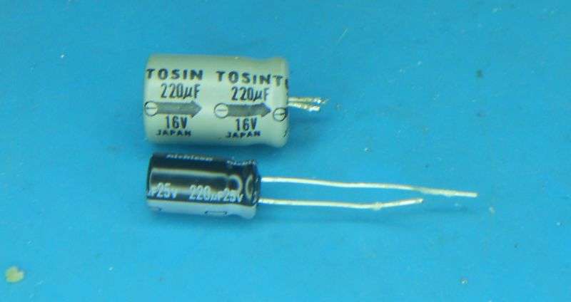
The smaller ones not so much.
Our policy for years has been a minimum voltage rating of 25 Volts for replacements in a 12-Volt radio. Except for some reallly large capacitance values. Mike has the same attitude. You'll be pulling out parts rated at 6,12 or 16 Volts. The higher voltage rating just improves longevity.
I prefer to change between 8 and 10 parts one at a time from one area at a time. Does simplify clipping the excess lead wires.
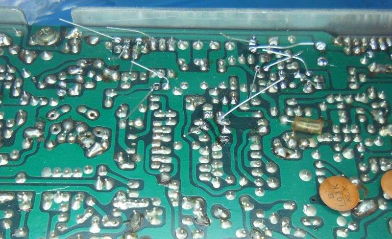
While we're in this vicinity of the radio, I'll mention an oddity that has prompted questions in the past. No, the radio was not built with C402 installed. That spot is blank.
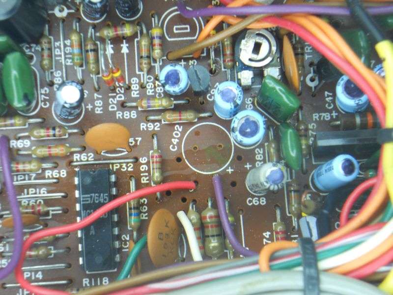
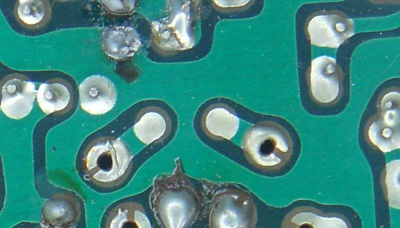
The foil pads under it lead only to a pair of pads meant for a wiring-harness connection. The small gap in the smaller pads here was a design quirk of Uniden's pc boards. A pad meant for a stranded wire had that gap. Maybe someday somebody will explain that one to me. All that tells us here is that C402 was connected to two harness wires and to nothing else.
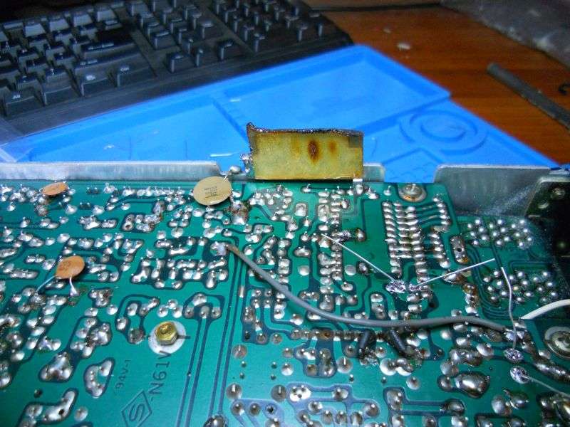
There is one cap hidden under a shield in the PLL corner. We don't put that shield back. Best I can tell it's to keep the radio from bleeding your television while the radio is receiving. Not worth the trouble to put it back, IMHO.
YMMV.
It really does pay to change them one at a time. Avoid the temptation to remove a handful. Too much potential to get the wrong part in the wrong spot. One-at-a-time may seem inefficient, but not nearly so much as troubleshooting an issue caused by the wrong part.
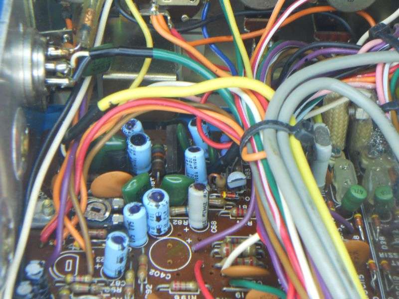
One of the hazards of this project is finding the right two foil pads for the cap you're removing. Just melting the solder with a finger on top of the cap will reveal the right spot if you see the lead wiggle when you push on it. If it doesn't wiggle, you found the wrong foil pad. We use a Hakko powered solder sucker. The wrong pad will get the solder removed a few times in a job this size. Just be sure to resolder any spots that got disturbed in error.
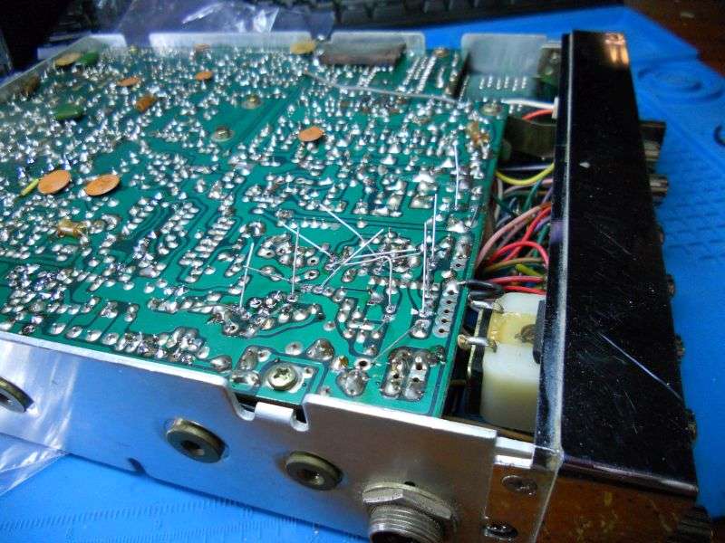
As always, a bright light and a magnifier applied after you're done will reveal any solder bridges between foil pads, or unsoldered pads that need to be resoldered. The bigger the magnifier the better.
A radio this old may have other problems. The empty crystal socket in one pic reveals a bad 7.8025 MHz carrier crystal. That's the next task for this radio before it can go home. Both the 7.8 MHz carrier crystals will get replaced with a tiny circuit board bearing a frequency synthesizer.
Film at 11.
73
In a way. Aluminum electrolytic capacitors have a finite life span. And a radio with dozens of them inside can develop a whole spectrum of quirks and outright failures as they fail.
Problem is, the age alone is not the only factor. Mileage counts. A new-in-the-box 1980 radio probably works okay. The same model that spent 20 years in a truck cab, on the dash baking in the sun every summer will have failed parts sooner than a radio used only indoors. Tube-type radios generage a lot of internal heat. They tend to wear out electrolytic caps faster than most solid-state radios.
And the initial quality of the parts is a factor. There's just no good way to pin down how it will affect any one radio.
Bottom line, if the radio is 30 years old, you may only find one or two of those caps with a problem. At 40 years old, it's pretty likely. At 50 years old it's nearly guaranteed.
Odds. Probabilities. And if you want a 40 or 50 year-old radio to be dependable, you need to just bite the bullet and change all of the electrolytics in a radio that has any significant mileage on it. Too bad there's no odometer to base that judgement.
This radio is a Cobra 138XLR. A 40-channel sideband CB with the uPD858 PLL chip. This technology lasted about one year. The FCC figured out how easy it was to get channels that are not legal from it. The radio was made by Uniden, and the pc board inside it was sold with Cobra, President, Robyn RatShack and other names on the outside. By 1979, this design was replaced with new models that had channel selectors and PLL chips that were more locked-down from getting more than 40 channels.
It won't be 50 years old for a little while yet. But it's old enough to get the re-cap treatment.
I'm using a kit from Klondike Mike. There's a good chance I have all the caps it needs in my shop's stock, but the labor to pull them off the shelf make's Mike's package price look good in comparison. The kit shows up in a small zip bag. No, you don't need a pic of that. A list of what's inside is posted on the web. A small card with the URL is included with the parts. Fair warning, the PDF with the list inside is password protected. The password will be on the card with the URL packed in the bag. I won't show any pics of that, since this list is part of what you're buying along with the parts.
They're all packed into a single zip bag.
Disclaimer: Not every radio with this circuit board uses the same cap kit. Mike lists one for this radio, but I was impatient and used a kit already on hand marked for the Realistic TRC-457. Yes, same circuit board, but it's a base, not a mobile. Turns out there are other small differences. Ended up with unused parts. That's to be expected. Also ran out of another. Not Mike's fault. I had them in stock, so it wasn't an issue. But if you don't have that kind of inventory on hand, be sure to order the kit for the exact model you want to rehab. Lesson learned.
IIRC this kit contains 51 parts. The correct kit for the 138XLR probably contains a shorter list.
My preferred method is to mark a snack-size zip bag with the value of each part that appears twice or more on the list.
There are a few 'single's, with a capacitance value that shows up only once on the list. They get put together in one bag.
The intent is that as I remove a part from the circuit board and read the value off of it, the new one to replace it is marked on the bag where it's found. It can't hurt to eyeball the schematic callout printed next to the empty spot and check Mike's list. That list may or may not be exactly right for every production run. If you pull out a 1uf cap and Mike's list shows a different value for that callout number, use the one marked on the list. If you don't you'll run out of one value before you're done and have others left over.
Pay attention to the polarity marked on each part as you pull it out. Odds are the "+" on the circuit board will agree with the "-" marked on the cap. Now and again you'll find a misprint on the circuit board's screen-print legend. If the cap is marked opposite the polarity marked on the circuit board, believe *the part*, not the board's markings.
I do have one suggestion I need to pass along to Mike. He doesn't include tantalum capacitors, only the aluminum electrolytics. I'm okay with that, since tantalum caps don't have the lifetime clock ticking away like the aluminum 'lytics. Tantalums just last longer on average. But this radio has an almost-certain failure that has nothing to do with age. C179 is a 2.2uf 25-Volt tantalum. That 25-Volt rating is fine until you turn up the AM modulation. That puts peak voltages well in excess of 25 Volts across this part. Big surprise, it fails as an annoying short. Can be bad juju for the relay. It's made from unobtanium. We learned decades ago to replace C179 with a 35-Volt or higher cap any time we looked inside this family of radios. Since this is really a "must replace" part, I'll recommend he add a 2.2uf electrolytic to the list. Doesn't have to be a tantalum. For that matter, there are folks who will tell you to just leave it out. I don't. You decide.
Someone had already done it to this radio, but with a slightly-clumsy looking axial cap.
This is a large job that will probably take you more than just one continuous sitting. To keep track of what's been changed and what hasn't, we mark the top of every factory cap with a black Sharpie pen.
I adopted the habit of doing these re-cap jobs at home after my wife goes to bed. Don't need a full-blown service bench for this task. And it reduces interruptions. But it takes more than one evening to finish doing it this way. Marking the original parts prevents confusion about what's new and what's not.
Some parts are obscured by the wiring harness. Cutting the zip ties will help gain access to some of the caps.
Can't mark 'em if you can't reach 'em.
You'll see a size difference between new caps and 50 year-old equivalents. The tech has evolved over the decades. The largest capacitance values reveal the most shrinkage.
The smaller ones not so much.
Our policy for years has been a minimum voltage rating of 25 Volts for replacements in a 12-Volt radio. Except for some reallly large capacitance values. Mike has the same attitude. You'll be pulling out parts rated at 6,12 or 16 Volts. The higher voltage rating just improves longevity.
I prefer to change between 8 and 10 parts one at a time from one area at a time. Does simplify clipping the excess lead wires.
While we're in this vicinity of the radio, I'll mention an oddity that has prompted questions in the past. No, the radio was not built with C402 installed. That spot is blank.
The foil pads under it lead only to a pair of pads meant for a wiring-harness connection. The small gap in the smaller pads here was a design quirk of Uniden's pc boards. A pad meant for a stranded wire had that gap. Maybe someday somebody will explain that one to me. All that tells us here is that C402 was connected to two harness wires and to nothing else.
There is one cap hidden under a shield in the PLL corner. We don't put that shield back. Best I can tell it's to keep the radio from bleeding your television while the radio is receiving. Not worth the trouble to put it back, IMHO.
YMMV.
It really does pay to change them one at a time. Avoid the temptation to remove a handful. Too much potential to get the wrong part in the wrong spot. One-at-a-time may seem inefficient, but not nearly so much as troubleshooting an issue caused by the wrong part.
One of the hazards of this project is finding the right two foil pads for the cap you're removing. Just melting the solder with a finger on top of the cap will reveal the right spot if you see the lead wiggle when you push on it. If it doesn't wiggle, you found the wrong foil pad. We use a Hakko powered solder sucker. The wrong pad will get the solder removed a few times in a job this size. Just be sure to resolder any spots that got disturbed in error.
As always, a bright light and a magnifier applied after you're done will reveal any solder bridges between foil pads, or unsoldered pads that need to be resoldered. The bigger the magnifier the better.
A radio this old may have other problems. The empty crystal socket in one pic reveals a bad 7.8025 MHz carrier crystal. That's the next task for this radio before it can go home. Both the 7.8 MHz carrier crystals will get replaced with a tiny circuit board bearing a frequency synthesizer.
Film at 11.
73
Last edited: