Yeah. 5V is what the sam suggests at channel 19 but I found that I had the best activity with the slug at about midrange in its can but again, thats in the 2.5 to 3v range. Im gonna send you the sams for the 142...this one part shows what sams says to do with alignment whichnis obviously wrong.5v might be too high. Let's use ch20 as an example. If the VCO needs to be at 35.005MHz, the VCO's varactor needs enough range to make it go down to 34.765 ( for ch1) and up to 35.205MHz (for ch40). For this reason, the radio is set to ch20 and L13 is adjusted so that 35.005 happens at the middle of the varactors tuning range. When you get the upper channels to drop out, it is because the voltage is already too high, and by the time you get to the higher channels, it falls out of lock (either because the PD output is already maxed out and can't go any further or the crystal sees too much capacitive reactance). Edit to say that with the trimmer, this latter case is not possible, so its maxing out the phase detector for sure in your case)
Here is the tuning chart from the datasheet for a varactor (SVC251S, couldn't find chart for the actual one, but they all behave similarly):
View attachment 75551This chart may lead you to believe that 5v is in the center, but the pF scale on the left is logarithmic. Going from .5v to 5v changes the capacitance from about 40pF to about 12pF. Going up to 10v from there only changes that another 5pF. The most valuable part of the varactor is the first 5v. If you already have 5v at ch1, that's no good. I would recommend setting it for about 3v at ch20 and see how it behaves.

You are using an out of date browser. It may not display this or other websites correctly.
You should upgrade or use an alternative browser.
You should upgrade or use an alternative browser.
-
You can now help support WorldwideDX when you shop on Amazon at no additional cost to you! Simply follow this Shop on Amazon link first and a portion of any purchase is sent to WorldwideDX to help with site costs.
-
A Winner has been chosen for the 2026 July 4th Retevis RA89R Giveaway! Click Here to see who won!
Cobra 142 GTL
- Thread starter johne2hotty
- Start date
Yea, most manuals suggest 2.5v there. As long as you get it comfortably within the range where it doesn't drop out going from ch40 to ch1, you're good. It doesn't have to be set with any accuracy.Yeah. 5V is what the sam suggests at channel 19 but I found that I had the best activity with the slug at about midrange in its can but again, thats in the 2.5 to 3v range. Im gonna send you the sams for the 142...this one part shows what sams says to do with alignment whichnis obviously wrong.

We know the sams was wrong with 5v, no need to send that. I was only interested in the order in which things are aligned. Get them in the wrong order and one messes up the other. No need to attach anything, I'll just explain.
When aligning the oscillators, be sure to align USB first, then LSB, then AM. It must be done in that order.
Consider the 11MHz oscillator. CT3 will affect the frequency in all modes, but in USB, it is the only adjustment. If you were to align LSB, then go do USB, that would throw off LSB. Likewise at the 7.8MHz oscillator. If you key up and align AM TX and then go turn CT1 afterwards, the AM TX is off again. Just be sure you are doing things in the right order!
Thanks TM86! I see the 5v part. I see what they did there. Thats on ch40.
What do you get in AM TX on the 7.8MHz oscillator?
What do you get in AM TX on the 7.8MHz oscillator?

I'll have to check when Im back at the shop tomorrow. Why cant I upload PDFs?Thanks TM86! I see the 5v part. I see what they did there. Thats on ch40.
What do you get in AM TX on the 7.8MHz oscillator?
Are you mobile with a slow connection? Maybe you are hitting post before it uploaads? Might be a question for the mods.Why cant I upload PDFs?

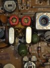
These are pics I took this afternoon. Maybe you can see something missing. Notice the capacitor soldered onto the filter stack that connects to a resistor? Below and slightly to the right of L13. I have not touched ct1 or ct2 yet. Cant get past first base.
We cant get internet service where we live. Using cell phone. I click attach files, it offers me just photos. I try to upload a pdf, it stops at about 15% and then the percentage disappears. I click post and it only puts up my conversation.Are you mobile with a slow connection? Maybe you are hitting post before it uploaads? Might be a question for the mods.
The box is really in nice shape. No holes, no abuse. But a real hack took place. Sad. I hate mods. You want uppers and lowers, buy a ham radio. I like radios to be set up clean and original.
Try waiting longer, even if it seems to disappear. It might be there is some timeout where the server gives up, I'm not sure on that. If the problem persists, drop one of the mods a message.We cant get internet service where we live. Using cell phone. I click attach files, it offers me just photos. I try to upload a pdf, it stops at about 15% and then the percentage disappears. I click post and it only puts up my conversation.
dxChat
- No one is chatting at the moment.