The colors are different than mine. on a Malaysia model its green orange blue. On your grant xl, did blue go to r174, white go to 8v c84/ic4, and red go to ground?

You are using an out of date browser. It may not display this or other websites correctly.
You should upgrade or use an alternative browser.
You should upgrade or use an alternative browser.
-
You can now help support WorldwideDX when you shop on Amazon at no additional cost to you! Simply follow this Shop on Amazon link first and a portion of any purchase is sent to WorldwideDX to help with site costs.
-
A Winner has been chosen for the 2026 July 4th Retevis RA89R Giveaway! Click Here to see who won!
Cobra 148 gtl 10 turn clairifier
- Thread starter red97k1500
- Start date
The wiper terminal (no. 2 in the photo above) should go to the varactor (thru R174 I believe on your 148).
The 2 outer terminals should go to either ground (thru R175 I believe on your 148) or 8vdc power.
If the clarifier does not slide the “right way” when turning, reverse the 2 outside wires.
The wire colors and wiring of the potentiometer in the picture I added were all wrong.
73’s
David
The 2 outer terminals should go to either ground (thru R175 I believe on your 148) or 8vdc power.
If the clarifier does not slide the “right way” when turning, reverse the 2 outside wires.
The wire colors and wiring of the potentiometer in the picture I added were all wrong.
73’s
David
Ok got it, yes I still believe I need too swap the two rear wires, I looked at a redrawn schamtic and I have it wired wrong... I need to put the blue wire to the wiper which is the one that goes to r174, and then the orange wire 8 volts,to the rear terminal.then I am confident it will work right. I guess that’s what I get for following internet instructions. The picture I followed has it wired wrong.
Thanks
Thanks
I just used a factory chrome plastic knob and drilled it out with a 1/4” drill bit, and it has a snug press fit on the shaft, but not so tight that you can’t pull it back off.What did you do about the knob?
How many KC's can you slide? Half 5 or whole 10 ? I am curious because my slider is wild.
I can’t remember I will check when I can get back to the radio... I will say that adding the ten turn did not affect how much it will slide. My clairifier is wild also,it slides a lot...adding the ten turn helped with drifting. My radio will drift about 100hz slowly over a couple hours
red97K1500,adding the ten turn helped
I am guessing you have the 10 turn potentiometer working correctly now?
A quick note about this potentiometer, it is half the value of the potentiometer supplied by the factory (10 turn 10k vs. 1 turn 20k). If you removed the resistors and jumpered some of them as suggested by "others" that could be part of the touchiness of the clarifier.
Just my opinion, I find that half a channel plus and minus is more than enough-provided you have a working channel selector.
")
73's
David
I just used a factory chrome plastic knob and drilled it out with a 1/4” drill bit, and it has a snug press fit on the shaft, but not so tight that you can’t pull it back off.
I can’t remember. I will check when I can get back to the radio... I will say that adding the ten turn did not affect how much it will slide. My clairifier is wild also,it slides a lot...adding the ten turn helped with drifting. My radio will drift about 100hz slowly over a couple hours
Does it stabilize eventually because once it heat soaks it should be relatively stable. I have not messed with my mobile other than try to remember to keep it at a precision 12 o'clock. I will have to look at how far this one goes once I put it on the test set. Think my slide need a little attenuation
") .
.since this is becoming a good reference thread for the 148gtl clarifiers, i will add this little tidbit in for those contemplating a 10 turn pot:
first, the shaft on these pots is a 1/4" rounded shaft and the radio knob will have to be drilled out to accommodate it as mentioned earlier in the thread.
the best way i have found to do this and not have the knob look off center or 'wobbly' when turning (AKA to get a truly centered hole that is straight) is to use a drill press.
if you don't have one, and can't come up with the 50 bucks to buy one used, then im sure you have at least one CB friend who has one.
getting these results with a hand drill will be an exercise in hope and karma.
set your drill press up with a 3/4" piece of sacrificial wood centered on the base.
chuck up the drill with a 1/2" drill bit (im guessing here and it could be a little more or a little less).
now with your sacrificial wood clamped securely in place, drill a hole in the wood all the way through.
after this step you don't want to change the orientation of the drill bit or the wood.
now chuck up the drill with a 1/4" drill bit. set the depth of the drill cut so that it will cut through the wood block about 1/4" deep.
now take your radio's knob and place it upside down in the hole you created.
it should go about halfway down and then wedge itself in place.
if it is too loose to be held securely, then use a little electrical tape to shim the knob up to size. it has to stay put in the wood and not turn.
now you can drill out the hole in the back of the knob and it will be centered and straight. if the drill didn't cut deep enough, re-set the max depth another 1/16" and keep stepping up until you drill deep enough to remove all the knurls inside that hole.
i have found when doing this that the knob pushes on the shaft of the 10 turn pot snugly and without the need for any adhesive or shimming.
if you do need to use adhesive, do yourself a favor and use rubber cement so you can remove the knob later.
hope this helps!
LC

Thanks LC.
I feel the need to add a caution about enlarging the face plate for these type mods.
I am not talking about the plastic bezel but about the metal structure behind the bezel.
Careful measurement here counts. If you are the type to measure it with a yardstick, mark it with a piece of chalk and cut it with a chisel, you will not get a good result. I.e. you may have to carve out the plastic bezel to get the knob installed and enable it to rotate if you do not make precise measurements.
Slow and steady is the way.
73's
David
excellent point Dmans!
i forgot to mention about enlarging the hole on the metal bezel.
yes, that will need to be done to accommodate the 10 turn pot.
the best way to do this is to use a step bit.
for those that aren't familiar with that term, here is a pic:
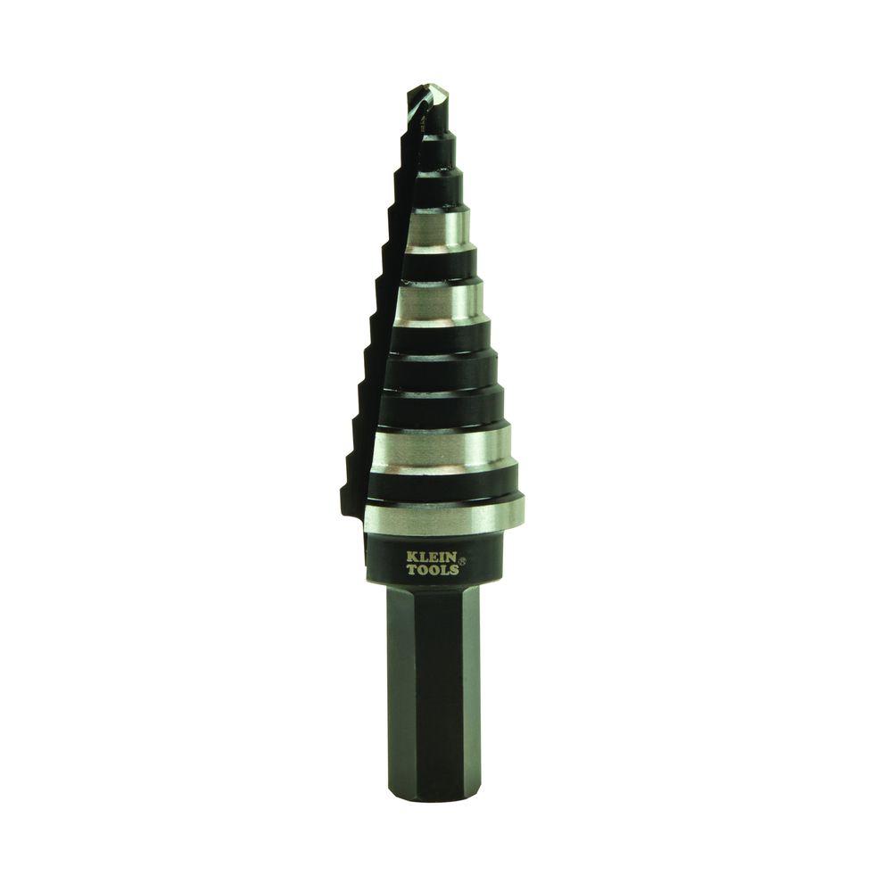
just enlarge the hole one standard size (one 'step') and you should be good.
trying to do this with a regular drill bit will usually lead to a slightly off-center, triangular-ish hole, and it's going to grab and kick like a b****.
the step bit will cut a nice round hole of the exact size you need.
LC
i forgot to mention about enlarging the hole on the metal bezel.
yes, that will need to be done to accommodate the 10 turn pot.
the best way to do this is to use a step bit.
for those that aren't familiar with that term, here is a pic:
just enlarge the hole one standard size (one 'step') and you should be good.
trying to do this with a regular drill bit will usually lead to a slightly off-center, triangular-ish hole, and it's going to grab and kick like a b****.
the step bit will cut a nice round hole of the exact size you need.
LC
Update: I never was able to get the clairifier to track from left to right ... so I just rewired it the way I originally had it... at least it works that way
I made this out of a step bit, a compression fitting and an old handle. It's great for making holes in plastic and works in metal to enlarge a hole. 
Step drills are VERY cool and make working on problems MUCH easier.
Someone before you has mangled a hole for a switch - as an example - easy fix for the step drill.
Cuts the burrs off too.
Someone before you has mangled a hole for a switch - as an example - easy fix for the step drill.
Cuts the burrs off too.
Update: I never was able to get the clairifier to track from left to right
red97k1500,
I have never been able to change a clarifier potentiometer without re-aligning the oscillators to "center up" the transmit/receive frequency when the pot is in the center.
73's
David
dxChat
- No one is chatting at the moment.