
You are using an out of date browser. It may not display this or other websites correctly.
You should upgrade or use an alternative browser.
You should upgrade or use an alternative browser.
-
You can now help support WorldwideDX when you shop on Amazon at no additional cost to you! Simply follow this Shop on Amazon link first and a portion of any purchase is sent to WorldwideDX to help with site costs.
-
A Winner has been chosen for the 2026 July 4th Retevis RA89R Giveaway! Click Here to see who won!
cobra 148 unlock PLL
- Thread starter Robalo
- Start date

Did not work that step L19 and L20 are not working. TP9 I have 6.5 volts replace r95 c79 c80 c80 c82 c91 c92 and ic1 and ic2 again  TR AND RX switching is working fine the problem maybe is ocillation on the vco team 1 and 2 with 3 and 4 on ic 1 are not switching on .
TR AND RX switching is working fine the problem maybe is ocillation on the vco team 1 and 2 with 3 and 4 on ic 1 are not switching on .Wow, ok...
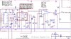
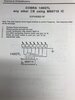
If nothing (no gating ) check voltages on those pins? Refer back to this graphic if needed...

Then look at PLL Pin 6 - measure at the pin, it should go HIGH - as in show 8 volts - that's LOCK.
Pin 5 is the "charge pump" to affect the "gating speeds" between the two pairs of 1 - 2 and 3 - 4. It (Pin 5) shoves it into Pins 3 - 4 then those pulses daisy chains thru and out to TP9.
Then you should check to see in the 10.240 is getting cleaned up enough to be used. Pin 8 (out) with Pin 7 as input from Xtal. If it's weak or not strong enough or just plain mush, it can't clean it up so Pin 8 shows nothing.
If pin 8 is dead - you need to check this with another Xtal...
Else Measure at TP 4 you should have a frequency.
If not then -again- its' below into L21 mess and that tripler is suspect.
Do continuity checks, note the voltages - we need to see if TR29 is getting pulled down by something...
You've gotta be having 33~35MHz ripping thru there somewhere...
If nothing (no gating ) check voltages on those pins? Refer back to this graphic if needed...
Then look at PLL Pin 6 - measure at the pin, it should go HIGH - as in show 8 volts - that's LOCK.
Pin 5 is the "charge pump" to affect the "gating speeds" between the two pairs of 1 - 2 and 3 - 4. It (Pin 5) shoves it into Pins 3 - 4 then those pulses daisy chains thru and out to TP9.
Then you should check to see in the 10.240 is getting cleaned up enough to be used. Pin 8 (out) with Pin 7 as input from Xtal. If it's weak or not strong enough or just plain mush, it can't clean it up so Pin 8 shows nothing.
If pin 8 is dead - you need to check this with another Xtal...
Else Measure at TP 4 you should have a frequency.
If not then -again- its' below into L21 mess and that tripler is suspect.
Do continuity checks, note the voltages - we need to see if TR29 is getting pulled down by something...
You've gotta be having 33~35MHz ripping thru there somewhere...
Attachments
ok IC 1 PIN 8 IS 10.240140
IC1
PIN 1 6.56 V
PIN 2 3.30
PIN 3 0.44 MV
PIN 4 8.28 V
PIN 5 8.28 V
PIN 6 0.160 MV
PIN 7 4.45 V
PIN 8 4.36 V
PIN 9 8.32 V
PIN 17 3.60 V
TR 29
B 0.783 MV
C 8.23 V
E 1.5 V
TR 20
B 33.392 MHZ MHMM
more checking tonight
IC1
PIN 1 6.56 V
PIN 2 3.30
PIN 3 0.44 MV
PIN 4 8.28 V
PIN 5 8.28 V
PIN 6 0.160 MV
PIN 7 4.45 V
PIN 8 4.36 V
PIN 9 8.32 V
PIN 17 3.60 V
TR 29
B 0.783 MV
C 8.23 V
E 1.5 V
TR 20
B 33.392 MHZ MHMM
more checking tonight
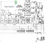
Look in graphic...
Got some answers - but need more input...
I've got questions...see in graphic for them...

Got some answers - but need more input...
I've got questions...see in graphic for them...
here we go late night
TR 20
B 4.09 V
C 8.30 V
E 3.48 V
TR 29
B 0.771 V
C 8.24 V
E 1.489 V
L 21 continuity yes on those pink dots and no legs short to case.
now frequency on the red dot 33.395 mhz.
all test made on channel one on AM band
thank you i for all tech support 73's
TR 20
B 4.09 V
C 8.30 V
E 3.48 V
TR 29
B 0.771 V
C 8.24 V
E 1.489 V
L 21 continuity yes on those pink dots and no legs short to case.
now frequency on the red dot 33.395 mhz.
all test made on channel one on AM band
thank you i for all tech support 73's
Hi @Robalo
Stop working on the radio here for a moment...
PLL install looks good, your VCO is working, you have an oscillation...
Now, because of Pin 6 - you are LOCKED Out because of something...
So let's look at the PLL pins for the CHANNEL selector.
Can you set a Logic Pins setting manually? Like make it channel 10 or 9 or 19? Just so you can get Pins 1-2 and 3-4 to work - they won't send or do anything unless there is a proper programming on the pins for your CHANNEL - they don't have anything to divide with...
Once you get VALID pin programming from the Channel Selector - those Pins 1-2 and 3-4 will start working.
Then we need to find that other frequency off of L21 to make it work. Tr20 doesn't have any input from L21.
So if TR20 is awaiting for the other half - start looking at L21 and TR29.
Right now, your PLL seems to be ok, not sure if it has a "Correct" logic input of a channel - that can explain why Pins 1-2 and 3-4 are not oscillating - wrong programming on Channel Selector input pins of the Pin 17 side. It will set a flag on Pin 6 and lock out.
So you'll have to verify a PROPER logic Pin input setting to make sure that the other half of the chip will work... Pins 1-2 and Pin 3-4 don't always equate back to the VCO as it works. The VCO is running, just not synced with the PLL and it's loop.
Last edited:

Pin 6 does show out of lock, but what is the programming pins - I mean, what channel are you on?
You done with the VCO as I see it - but you need PLL programming to set the gating function and its' ability to track/control that VCO to remove the lock - your 6.57 volts. Kinda tells me it "wants to set" the lock, but what is there holding that lock line high? You're 1.5 volts BELOW the 8V you set on your power supply feeder on Pin 6. So that tells me the PLL isn't going to be fooled...
 It's high enough difference trigger-wise to keep you locked out of the MB3756's ability to TX and RX - now I do see an 8V supply are you putting that into the board to offset the MB3756? At least you proved you have RX TX switching - you just have the PLL issue....I hope I see that in your Vids here...
When you add on a power supply feed, that changes the results of the test. so are you holding the Lock line high while you do this? Your Red light does go on, you did get that done but your PLL won't let you get past that...
If that is the case - your PLL chip is pulling it back down...Your 6.57 volts is sinking current not zero yet, but it's trying to pull something down. So it tells me "I'm not in lock" even though someone is trying to defeat it...The PLL is shut down...it won't let you bypass that.
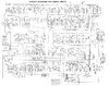
What is R163 doing? (22K by MB3756) What is it reading - the voltages - one side to the other... because it's fighting you on something...(Remove that power supply feeder for this test...) Measure at the Resistor and back at the Diodes UNBANDED end towards the front of the board - you may want to do a continuity check too... make sure that trace - being so close to the front panel - is not blown open or has solder on it pulling current from an adjacent trace...along the tine all the way back to the MB3756 too...
See graphic, that "Lock Line Pull-up resistor" R163, 22K is back at the MB3756...

You done with the VCO as I see it - but you need PLL programming to set the gating function and its' ability to track/control that VCO to remove the lock - your 6.57 volts. Kinda tells me it "wants to set" the lock, but what is there holding that lock line high? You're 1.5 volts BELOW the 8V you set on your power supply feeder on Pin 6. So that tells me the PLL isn't going to be fooled...
When you add on a power supply feed, that changes the results of the test. so are you holding the Lock line high while you do this? Your Red light does go on, you did get that done but your PLL won't let you get past that...
If that is the case - your PLL chip is pulling it back down...Your 6.57 volts is sinking current not zero yet, but it's trying to pull something down. So it tells me "I'm not in lock" even though someone is trying to defeat it...The PLL is shut down...it won't let you bypass that.
What is R163 doing? (22K by MB3756) What is it reading - the voltages - one side to the other... because it's fighting you on something...(Remove that power supply feeder for this test...) Measure at the Resistor and back at the Diodes UNBANDED end towards the front of the board - you may want to do a continuity check too... make sure that trace - being so close to the front panel - is not blown open or has solder on it pulling current from an adjacent trace...along the tine all the way back to the MB3756 too...
See graphic, that "Lock Line Pull-up resistor" R163, 22K is back at the MB3756...
HandyAndy, forgive me for butting in...
I see the point that you are trying to make and wanted to try a slightly different approach... absolutely no disrespect intended....
Robalo,
In an attempt to make these PLL chips harder to expand... the makers have kind of "added on safety checks" through the years. A long time ago, you could expand one by taking hardwired pins on the chip, cutting the PC board copper and tying them high or low through switches and the PLL would respond with a little more range on the Pd output (lower or higher) thus driving the VCO wider in range....giving you extra channels. The PLL had no way of knowing what a valid switch pattern was .... or was NOT.
Later PLLs have added ROM memory internally. This means that they can now TELL what a valid switch pattern IS..... and ignore the rest. So, nowadays, if the PLL gets an invalid switch coding...it will respond with an unlocked condition which in many radios.... disables the world. Unfortunately....the PLL can't tell when someone has hacked in to add a new switch pattrern..... OR a FAILURE has occurred ( a cable, a pull-up/pull-down resistor, solder joint).... it just can't tell.
That is why HA is pushing on having you check the switch / PLL programming pins. If something is out of kilter in there... the PLL will likely show UNLOCKED...to kill everything!
Best of luck to you,
Bob
I don’t want to used this radio for donor parts . I need to know the problem there is to many radios with 6.5 volts on TP9 up there . Thanks Andy and Bob and every body following this fix
I know we getting closed right pal !
I know we getting closed right pal !
Whew...was not sure if we were going to try to EMULATE a Lock - but now I see with your trying - you have got pretty much your ducks in a row now...
Here's the rub though. You will need to start plugging in some type of program pin setting to even get the "gate" pins - those 4 we talked about earlier - and have it even try then, to look at the 33 - 35MHz signal the VCO sends.
But remember - the VCO is getting sent a signal from the PLL as ADDED bias to the Varactor bias as a correction signal in that loop from the VCO - so it will eventually send thru TR20 - back to Pin 17 - a frequency up to 2MHz to as low as 10,000 cycles per second - even less - but it has to see that on Pin 17 to open the Gates to divide and check then correct on PLL's Pin 5 (Charge pump) daisy-chained thru to out on pin 1 and then onto VCO pin 5. So you only get one shot to make the Pin 17 active and make the gating function work to keep the PLL from locking you out as it tried to zero in on the correct voltage the varactor needs. It needs the pin programming on the other side to make this work. There is the need to have a pin or two active on that side to even tell the PLL to even start gating processes to even make the ROM check back and look into a valid divider input.
There is an internal loop in these that requires a VALID input that it checks - again, back to the "detent switch" (PLL Pin 6) it sees as a means to "Validate" an updated programing of pins for Divider Count. If you don't set a pin or two on the input divider - it won't attempt to "reset" Pin 6 and Pin 5 by itself to make the Gates run at any clock speed- and it'll just sit there...so you may want to invest in a method or "Breakout box" so you can set switches to review the outputs on the other pins as you work thru a means to obtain - whatever - it is your trying to get.
I hope I'm following you on this...
HA and Bob and everybody else, this is what you guys mean, finally I found my notes and I’m going for it. It’s been almost 2 years playing with this radio and it’s been quite a learning experience. When I start something I need to finish it, thank you for all your patience and helping me out with your support. We’re getting close I feel the heat! It’s a hobby it’s a passion and it’s a therapy.
Attachments
OK we got new R 163 22 k it read 8.35v to center of board or ic 1 pin 9 and to the other size it read 0.735 v. i replace tr 47 because base has 5.22 v.i feed r 163 with 8 v and tx at 26.812 mhz
There are two ways I can read the above...
One is you're getting a TX frequency...
Other is - and I don't know - if you have reconnected the channel selector or not...
Either way, it looks like you're still out lock...when the other half of the resistor is low - the Diode on pin 6 of the PLL is sinking current - keeping you from TX-ing.
Ok, slow down, you just potentially Blew TR47 again - slow down...
A Base voltage of 5.22 means leakage from something you shouldn't have in there...So that line does communicate - just don't over do this...
Anything above 5 volts on that Base lead or TR47 means you can blow the part and have to replace a PNP again...Be Careful with that.
It (TR47) simply "samples" the Lock line - if it's high, that part acts as a clamp to shut down the audio to the Audio amp chip to silence the speaker. The R235 - 100K resistor limits current and stiffs the voltage into TR47's Base so it only needs to "sense" the lock line....
So as you play with this you just seen the 6.57 volts while you tried to tie the Lock Line Pin 6 line high as you attempted to defeat the Lock out - slow down or you will hurt your effort...that is what TR47 and TR53 do - turn off the Audio - so when you don't hear anything you know something's wrong...just don't keep throwing new parts in there - after every experiment - this can get expensive...
One is you're getting a TX frequency...
Other is - and I don't know - if you have reconnected the channel selector or not...
Either way, it looks like you're still out lock...when the other half of the resistor is low - the Diode on pin 6 of the PLL is sinking current - keeping you from TX-ing.
Ok, slow down, you just potentially Blew TR47 again - slow down...
A Base voltage of 5.22 means leakage from something you shouldn't have in there...So that line does communicate - just don't over do this...
Anything above 5 volts on that Base lead or TR47 means you can blow the part and have to replace a PNP again...Be Careful with that.
It (TR47) simply "samples" the Lock line - if it's high, that part acts as a clamp to shut down the audio to the Audio amp chip to silence the speaker. The R235 - 100K resistor limits current and stiffs the voltage into TR47's Base so it only needs to "sense" the lock line....
- IF you kept the 100K resistor in place you should be ok.
- You'll also notice it has a trace arriving to it from TR33 - that is the AM switch that uses the AM Mode selector and looks at the RX function to switch the Radios AM receiver on and feed power to its' portion of this receiver.
So as you play with this you just seen the 6.57 volts while you tried to tie the Lock Line Pin 6 line high as you attempted to defeat the Lock out - slow down or you will hurt your effort...that is what TR47 and TR53 do - turn off the Audio - so when you don't hear anything you know something's wrong...just don't keep throwing new parts in there - after every experiment - this can get expensive...
dxChat
- No one is chatting at the moment.
