
You are using an out of date browser. It may not display this or other websites correctly.
You should upgrade or use an alternative browser.
You should upgrade or use an alternative browser.
-
You can now help support WorldwideDX when you shop on Amazon at no additional cost to you! Simply follow this Shop on Amazon link first and a portion of any purchase is sent to WorldwideDX to help with site costs.
-
A Winner has been chosen for the 2026 July 4th Retevis RA89R Giveaway! Click Here to see who won!
Cobra 148GTL keyup AM, SSB with no Audio
- Thread starter PETERpH
- Start date
Just don't rush thru a step.
Patience with the Patient.
To help with Eye strain, use a Magnifying Glass as much as possible...
Look for shorts - In some of my own Documentation efforts, of radios I still have - I find several ones that my XYL owned and left behind - I can see why. Can't say who did the work, but if she tried, I can feel better knowing she tried, may not have helped - but she did try to apply herself - I can't fault anyone for that.

So I recommend a moment of DVM across the capacitors so you can verify a voltage difference exists - no voltage, may mean a dead short or blown part.
Patience with the Patient.
To help with Eye strain, use a Magnifying Glass as much as possible...
Look for shorts - In some of my own Documentation efforts, of radios I still have - I find several ones that my XYL owned and left behind - I can see why. Can't say who did the work, but if she tried, I can feel better knowing she tried, may not have helped - but she did try to apply herself - I can't fault anyone for that.
Not too long ago I posted something like this...
- There are several areas of concern, one being - if you recognize the bottom of this board, you should, it's another 148 like yours, someone replaced the final - note that one in the middle - if the FINAL and its' Emitter leg when it was soldered, even BONDED the Boards Power Grounds - to Chassis back panel - which contained a tab to hold the board and also provide a RF current to go - but keep DC contained to the main PCB.
- This board was made in the years Uniden had made "Insulated" chassis radios designed for Mobile use. Some vehicles back then had used a Positive Ground ignition system - the power wires were used and when you bolt the antenna on, the bracket to the mounting location - the radio's DC power has to be INSULATED from the EARTH ground - so they used these tabs to allow RF to circulated thru in and out of the radio - but keep DC voltages from causing a dead short.
- In the above, that would have caused an epic fail - possibly blowing the traces from the power supply feeder lines and even the opening up the power switch contacts.
- I've had Family member with the notorious ability to take brand new things and burn them up by attempting to wire up to their vehicles ignition - only to burn up the radio beyond warranty repair simply because they were in a hurry and didn't pay attention to details - lesson learned - but a D*mn good radio got burned up in the teaching moment.
So I recommend a moment of DVM across the capacitors so you can verify a voltage difference exists - no voltage, may mean a dead short or blown part.
Just don't rush thru a step.
Patience with the Patient.
To help with Eye strain, use a Magnifying Glass as much as possible...
Look for shorts - In some of my own Documentation efforts, of radios I still have - I find several ones that my XYL owned and left behind - I can see why. Can't say who did the work, but if she tried, I can feel better knowing she tried, may not have helped - but she did try to apply herself - I can't fault anyone for that.
Not too long ago I posted something like this...
So as you work thru the process, look for simple things; you did have that radio apart - there's items that may have been moved, pushed back, adjusted or ignored because of the initial effort was to re-cap a radio In doing that, you may have overlooked another condition that can occur - foil trace tearing - where the solder pads "lift" from the board for the adhesive behind the pad, designed to hold it in place, loosens and lifts - it can tear the trace in two from the removal, insertion and resoldering - and considering the age, this is a more probable condition that not.
- There are several areas of concern, one being - if you recognize the bottom of this board, you should, it's another 148 like yours, someone replaced the final - note that one in the middle - if the FINAL and its' Emitter leg when it was soldered, even BONDED the Boards Power Grounds - to Chassis back panel - which contained a tab to hold the board and also provide a RF current to go - but keep DC contained to the main PCB.
- This board was made in the years Uniden had made "Insulated" chassis radios designed for Mobile use. Some vehicles back then had used a Positive Ground ignition system - the power wires were used and when you bolt the antenna on, the bracket to the mounting location - the radio's DC power has to be INSULATED from the EARTH ground - so they used these tabs to allow RF to circulated thru in and out of the radio - but keep DC voltages from causing a dead short.
- In the above, that would have caused an epic fail - possibly blowing the traces from the power supply feeder lines and even the opening up the power switch contacts.
- I've had Family member with the notorious ability to take brand new things and burn them up by attempting to wire up to their vehicles ignition - only to burn up the radio beyond warranty repair simply because they were in a hurry and didn't pay attention to details - lesson learned - but a D*mn good radio got burned up in the teaching moment.
So I recommend a moment of DVM across the capacitors so you can verify a voltage difference exists - no voltage, may mean a dead short or blown part.
Hi Andy. I am comparing capacitor direction from the image you send me from inside your radio. I know as C232 ground (-) on my radio is facing away from the radio chassis but yours (I am not sure) is facing the chassis. Do you have an other image from the section near the TA7222? to compare the capacitor direction.
Thank you.
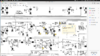
Just for some comparison for you I have a 148 board so I took a pic of the section for you.Hi Andy. I am comparing capacitor direction from the image you send me from inside your radio. I know as C232 ground (-) on my radio is facing away from the radio chassis but yours (I am not sure) is facing the chassis. Do you have an other image from the section near the TA7222? to compare the capacitor direction.
Thank you.


C186 note Positive (+)

A view from right next to TR41/TR42 BEHIND power choke...

A view of the Mic Amp area
Audio Chip is to the LEFT in photo...
Photo is From Final Driver Area towards front
I have them all correct, I even verify the schematic. I constantly keep on going back to this point. Where TR-13 point 14 should be 0v but there is 9.43v all the time. at TR13 squelch range it should be .65v-8.11 open squelch is 9.43 close is 8.13v I don't think it should be like that, not according to the schematics. I am keep on looking.
Attachments
It says 0V PA, but doesn't mention anything about in standard RX. In the 2000 service manual the parts are the same, but the voltages listed are slightly different with point being 2.95V PA and 7.65V.I have them all correct, I even verify the schematic. I constantly keep on going back to this point. Where TR-13 point 14 should be 0v but there is 9.43v all the time. at TR13 squelch range it should be .65v-8.11 open squelch is 9.43 close is 8.13v I don't think it should be like that, not according to the schematics. I am keep on looking.
The columns on TR12 and TR13 below are as follows
Mode/E/C/B (voltage RX) E/C/B (voltage TX)
Then check your Squelch control Pot, locate the pot, using the DVM, test all three leads from the Squelch control on the front panel, at the pot on the front [panel - make sure there are voltages on them.
Check them to a simple board ground - like a IF case can shield - simple ground.
Then post those results here.
Next stop, TR19 - that audio amp that sends the results from the ANL side or the SSB conversion - to the Volume Control...
@999 - getting kinda busy here, thanks for sliding in!
Check them to a simple board ground - like a IF case can shield - simple ground.
Then post those results here.
Next stop, TR19 - that audio amp that sends the results from the ANL side or the SSB conversion - to the Volume Control...
@999 - getting kinda busy here, thanks for sliding in!
Last edited:
dxChat
- No one is chatting at the moment.