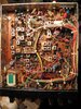
• You can now help support WorldwideDX when you shop on Amazon at no additional cost to you! Simply follow this Shop on Amazon link first and a portion of any purchase is sent to WorldwideDX to help with site costs.

Cobra 148GTL keyup AM, SSB with no Audio

If the radio was receiving properly before the parts got replaced, this raises a really tall flag.

Odds are that the change in the receiver was caused by the process of replacing those parts. A really bright light and a magnifier will probably reveal a solder "bridge", a tiny finger of solder between two foil pads that are supposed to be separate.

The status LED on the front should be green while receiving. If it goes dark, this is a big hint where to look next.

73
 
  • Like
Reactions: tecnicoloco
Update. I received the caps and replaced them, voltage still a little high, but stable. All the channels that were not working, now they do.
I can see modulation on the Oscilloscope BUT I can't hear anything ONLY white noise. (Soft white noise). I unplug the antena to the dummy load and is the same white noise.
I have check from the TA72222 to TR-43 AGC AMP CI-183, CI-187, TR-19 SSB DET AM AF AMP. I removed all of these ceramic capacitor to check them of the board IC-72, IC-75, IC-71, TR-13, TR-12... everything looks good.

I purchased a Tektronix CFC250 frequency counter for this project and other testing equipment. I recheck everything from what I check last week with the Oscilloscope, everything looks to be normal. At this point I am looking forward to fix it and continue to learning and understanding more of electronics....


Does any have an idea of what could be?


Wow, you did a lot, now you'll have to go back and double check the work you did.

Ok, remember that Truth Chart I posted in this thread? The 2nd one in that post, note the TP1 frequencies...

When you hear white noise - think thru the areas you worked on, you may need to go back and use your scope to determine if you have the frequencies listed on that Truth table chart.

You see modulation - you may have soldered a cap back in, but it may not be correctly installed or the right value.

As per your post, I'd look into the Receiver side. You have your PLL generating a approximate 34 to 35MHz signal - you seem to have channels, and you seem to have modulation - the only way to truly know that is to have another radio set up to monitor - you'd hear your audio thru that radio when you're listening on the same channel your talking on - when you key up your 2000...

When you receiver is quiet, it sounds like you've disconnected a cap or replaced that cap incorrectly - it's not sending signal to help you find the channels.

The PLL - it pipes Intermediate frequency (your IF from L20) to the Receiver side - if that signal isn't there, you don't have any receive - it just sits there and you hear a white noise hiss from the rest of the radio waiting to have a signal sent into it.

TR15 is your main Receiver 1st IF amp - it uses that 34 to 35MHz signal here, you have a cable that routes to it from L20 and that big shrink wrap area of parts by it.

Might want to make sure you've got your parts back in right.
 
  • Like
Reactions: Dmans
If the radio was receiving properly before the parts got replaced, this raises a really tall flag.

Odds are that the change in the receiver was caused by the process of replacing those parts. A really bright light and a magnifier will probably reveal a solder "bridge", a tiny finger of solder between two foil pads that are supposed to be separate.

The status LED on the front should be green while receiving. If it goes dark, this is a big hint where to look next.

73


The light it is green while on RX... no dim light or darkness. it is odd indeed.
 
Wow, you did a lot, now you'll have to go back and double check the work you did.

Ok, remember that Truth Chart I posted in this thread? The 2nd one in that post, note the TP1 frequencies...

When you hear white noise - think thru the areas you worked on, you may need to go back and use your scope to determine if you have the frequencies listed on that Truth table chart.

You see modulation - you may have soldered a cap back in, but it may not be correctly installed or the right value.

As per your post, I'd look into the Receiver side. You have your PLL generating a approximate 34 to 35MHz signal - you seem to have channels, and you seem to have modulation - the only way to truly know that is to have another radio set up to monitor - you'd hear your audio thru that radio when you're listening on the same channel your talking on - when you key up your 2000...

When you receiver is quiet, it sounds like you've disconnected a cap or replaced that cap incorrectly - it's not sending signal to help you find the channels.

The PLL - it pipes Intermediate frequency (your IF from L20) to the Receiver side - if that signal isn't there, you don't have any receive - it just sits there and you hear a white noise hiss from the rest of the radio waiting to have a signal sent into it.

TR15 is your main Receiver 1st IF amp - it uses that 34 to 35MHz signal here, you have a cable that routes to it from L20 and that big shrink wrap area of parts by it.

Might want to make sure you've got your parts back in right.


I appreciate your help...

I find few capacitor that I did installed wrong... I have replace them and seems with the same white... I did check TR-15 it is in good working condition, I have purchased a Atlas DCA55 just for that task.

I know as something different under R43 resistor without signal the voltage is correct. However when I press the PTT the voltage DROP!!!! I am trying to figure out why is doing it....


I am busy with School right now. I will continue updating as soon as I find something.

Thanks again.
 

Attachments

  • Screen Shot 2021-02-01 at 6.44.28 PM.png
    Screen Shot 2021-02-01 at 6.44.28 PM.png
    140.7 KB · Views: 13
  • Like
Reactions: Slowmover
R43?

Hmm...Well, that resistor is AGC output for the PIN Diode section...from the same feed that RF Gain and Receiver gets, your RX switch from the MB3756 - that Regulator and Terminal Switch. One line is always "on" regulated to 8 volts, and goes to the PLL and runs the lights, the other two "toggle" one goes On when the Other Goes Off. RX and TX

The Radio uses the PTT and "looks" at PLL LOCK - if the two are good, the Radio then switches to TX mode.

RX voltage drops so the line that R43 COMES FROM - will drop to nearly ZERO volts. That is normal.

R43 sends power to the PIN Diodes when strong RF in the Receive is present - it's a part of the Radios AGC - this helps the RF amp from getting too much signal.

When you Transmit, Note D16, that comes from the TX line that sends power to TX sections - That diode forces the PIN diode section to stay on, and shunt all RF that the radios is transmitting - that the small Cap that RX uses from the Output Network as a Tap - it sends this into ground it's dissipating RF energy that would otherwise damage TR15 that RF amp - D16 allows the radio to use the TX lines power to do this.

D68 keeps that 8 volts from feeding back into the RX side thru R43 - it's a one way valve - power goes in one direction - towards D16 and the PIN diode section.

The how does the Radio even transmit 4 watts when it's dissipating all the RF right at that Tap Point?

It's the Value of the Cap that plays the role in how much signal the RX side sees. The bigger the Cap values are, the louder or stronger the receive. This is reciprocal for the TX side too, you want the Transmitter to send out RF, not cycle it back into the Receiver - so the PIN Diodes help protect the RF amp TR15 from that high level RF, but then allow low-level RF to pass into once the TX is done.

The problem lies in how big that cap has to be to make this work without sucking all the power down into the PIN section?

When the TX is done, there's not a lot of RF left (we hope) so the radio then powers up the RX line and R43 becomes active again - just enough power to "turn on those PIN diodes to act like Arrestors" - but not on Fully as like what D16 does.

This allows the AGC to make small changes to it's power levels - as you see in the S/RF meter when receiving - so the Radio doesn't blare out the volume of the signal yet too, not bury it in protecting itself from too much RF input.

That's why C31 is only 29 Pico Farad, or even less like 18 Pico Farad (pF) - that C31 cap keeps a lot of TX RF out of the RF amp circuit, but when in a High impedance state, allows the RF from the antenna to flow thru into the PIN and RF amp sections.

What do you mean "High impedance State?" I don't know how else to say or explain it, except when you apply that 8 volts to the Pin diode section - there's power at one leg of the cap from that D16 power feed - it's DC, the other end is RF as a given PEP level trying to pass thru that cap - in DC and RF mixing together, this sends a current across the cap into the PIN section and down into Ground. The RF is washed off the cap in this method by applying a STATIC voltage to the opposite side - this changes the way that cap now "looks" at RF currents. IT appears more as a short than a resistive element - so what little RF that can pass thru the 8 volts DC current - simply is dissipated in the PIN diode circuit.

Caps can act like "limiters" as a means to control the level of power that flows thru at any given time - the "Static" level of power the DC state, and the RF power on the other side - one blocks the other when that "other" side is low, when the other side has more power - it doesn't have ALL the power, just the DIFFERENCE in level between the applied DC power and the new input wave (RF Power) Arriving to it. So 8 volts from a sense 12~15 volts of RF power - leaves you with less power to dissipate than without having DC present to provide a mechanism to "swamp out" or wash away that RF signal from interfering with the RF amp and potentially damaging it.

PIN Diodes are basically a cruddy PN diode, only it has a very PHAT Intrinsic layer that is poor conductor material but works great as a means to shunt RF without having to dissipate a lot of watts and heat in doing so...
upload_2021-2-1_20-25-33.png

IT may not be the BEST answer but it is the best answer I can provide you with what little time I have to post this.

To help, you can see more about PIN diodes here...
https://en.wikipedia.org/wiki/PIN_d... known,hole's level it will begin to pour out.

or

PIN diode - Wikipedia
 
Update. I have found this voltage on the PA. and 0 volts on AM...


I cannot figure out where power is coming from. I believe this is my issue the radio doesn’t go back to RX.
PTT light is green


Does anyone have any idea?
 

Attachments

  • 7BB48664-A7DB-4FC4-A23E-D23CE6B9FC93.png
    7BB48664-A7DB-4FC4-A23E-D23CE6B9FC93.png
    346.8 KB · Views: 11
  • 51E6472E-751E-448E-B9CE-00FE4C7A6B41.png
    51E6472E-751E-448E-B9CE-00FE4C7A6B41.png
    225.1 KB · Views: 9
Ok, when RX doesn't return - suspect the "toggle" function not letting go.

So to verify that - what is your MB3756 doing?

Pin 1 should be your constant 8V - goes to the PLL - Pin 9.

RX is Pin 6 of that same chip.

So here goes...
upload_2021-3-9_21-23-9.png
Look at the bottom right pinout description​

So
  • Pin 1 Constant
  • Pin 2 Input Voltage (Power)
  • Pin 3 Ripple Filter (VREF) Helps smooth switch transition
  • Pin 4 Ground
  • Pin 5 Control Line (Floating = Pin 6 HIGH Pin 8 LOW Grounded = Pin 6 LOW - Pin 8 HIGH)
  • Pin 6 RX control (Switched using Pin 5 - OPEN/Floating)
  • Pin 7 KEY - NO Connection
  • Pin 8 TX Control (Switched using Pin 5 - LOW)
TR35 controls Pin 5 - uses itself as a comparator - IN PLL in lock - TX can occur...

upload_2021-3-9_21-31-52.png
So use this voltage chart to determine if your MB3756 is doing what it should.
You should at least have RX - not always TX.
If TR35 is doing it's job, it will release Pin 5 so you have voltage for RX to even happen.
If PLL is out of lock, no TX - but you can get RX back.
- so that means Pin 5 should change so Pin 6 goes back to HIGH (8V)

upload_2021-3-9_21-41-13.png

You still have several caps that can goof up your efforts - See brown circled above
back to your board - make sure they're in the right way!

C133 too!

Ok, the last question I have then, is to know if the RX/TX light - Green in RX...

But...what does it do when you TX? Does it change to Red, No? ok-don't worry, that's one status...

There's another - and no, it's not Yellow (well, it could be but that's a different story...:) )

The one I'm concerned with is, what does the RX light do when you key up your microphone?

Does it stay green - or go out?

Does your speaker go silent?

The above are clues as to our next step...
Once all the above has been addressed, we'll check out the PA switch...
 
Last edited:
  • Like
Reactions: Dmans
Thank you for your help Andy.
I verify the IC4 these are the voltages.
Pins

1) 9.36v
2) 13.02v
3) 13.02v
4) 0.0v
5) 13.02v
6) 9.57v
7) No pin on board
8) 0.6v

The TR35
TX
USB-LSB-AM had the same results
0.0v 0.07v 0.81v
RX also had the same results
9.0v 12.87v 9.26v

Capacitor C133 - C134 - C135. In good conditions all capacitors were replace at the beginning of the project. I double check all of them to make sure I did not made a mistake switching the connections. they are all good.

The light is green on RX. Red on TX.

––No Yellow light––

When I TX I can see the watts reflecting on the wattmeter. I can hear myself on my other radio. the oscilloscope shows modulation.


I can verily hear noise on the Internal and external speaker.

Thank you for your help!
 
Ok, were getting close, we now have to find those speaker wires...

The following is based on your Mic Wire pin socket being a 5-Pin plug.

The output of the Audio amp, since you can hear yourself on another radio - means it works - up to a point.

IT seems the speaker wiring and possibly the CB/PA switch is involved.

So next step would be to try and locate - even see if - MIC pin 3, 4 and 5 are working.

IF you get RX/TX light - it means Mic socket wires 4 and 5 are ok, we have to look at Mic Pin 3 and it's wires from the Mic socket back to the main board. They are Pin 3 - it's live from the speaker - the CB/PA switch routes to this wire or to the PA jack - the Speaker wire - since it's live - needs to complete the circuit, it uses Pin 4 at the Mic socket - to make the Speaker circuit complete.

When you're in PA mode, ALL audio routes to PA speaker jack - thru the CB PA switch - it turns off TR35 - so you don't key up the radio.

Please don't use Pin 2 for anything else but Mic audio wire ground - it needs to go somewhere.

Pin 4 is Common (board ground) for MB3756 (pin 5 toggle) and Pin 3 Speaker Return

What does this have to do with the CB/PA switch - a lot, one wrong wire placement and you lose all audio to both PA jack and EXT and Internal speaker.

We just have find where Pin 3 speaker return wire is.
 
Once I read your respond, my concern was the mic wiring.

I have a Road King 56 microphone.

Pin wire
1- White
2- Shield
3- Black
4- Red
5- blue

From the microphone board, pin 1 goes to Dynamike – pin 2 to the board to one of the pins from C106. Pin 3 green wire to rear speaker shield. Pin 4 to common ground to TA7222AP pin 3-4 pin counting from the back of the radio towards the front. pin 5 goes to CB/PA switch.

I also check for audio at the PA jack without any issues.

I try different microphone wiring diagrams from the internet without any luck.

:(
 
But you do get PA audio?

Both Pin 2 and Pin 4 would show as Ground at the JACK (pin side) - nearly a dead short to each other then retested to a shield can, like one of the main IF cans in there, it's case tests as a short - inside the radio - proving true Board ground.

Now with PA working - do you hear receive thru the PA? You couldn't transmit to the other radio - but can you hear the other radio thru the PA speaker when you talk on that other radio?

I'm trying to confirm that Receive works -

Do you have S meter showing indication?

When you key up the other radio you can hear it thru your radios PA speaker?

PA audio - you say you can hear yourself thru that Microphone - like Talkback - only thru the PA speaker.

With these three conditions, if yes, then - the wiring OF THE SPEAKER is suspect.
 
When I transmit with the radio I can hear myself on an other radio, I even ask for radio check and getting responds. (on channel 19–27.185)

Microphone pin 2 (shield) test on all IF caps making the sound of a short.
Microphone pin 4 (common ground) test it to all caps making the sound of a short on the voltmeter.

Test on both CB/PA jacks with an external speaker.
Talking on an other radio..

PA jack.
I can hear myself clear on all modes AM-SSB with the external speaker plug in the PA jack no problem.

• Speaker jack.
The S meter goes up to 7s units, once I talk the needle tend to drop. I cannot hear anything on AM but "I can" hear myself on SSB. (low audio comparing the test on the PA jack)

No S meter indication.

I purchase an Audio signal tracer on eBay at arrived today, unfortunately did not work!
 
WHEW, ok, then the TX side is done, let's go back to the basics of wondering where the RX went - you're good, the RX is not..

Remember the "replaced with new caps?" condition? You might now want to revisit that using that signal tracer - if you can figure it out and make it work.

Go back to the time when you replaced the caps - find those ones you changed - see if they are ok, I know you checked earlier, but it seems odd that your radios' TX works, some of the Caps just might be in backwards and you just need to revert them to the correct orientation.
 
That is exactly what I was doing. I have found that there are no marks on the board of + from C132 and C148. I am going to flip them and see if I get something.
 
Ok, be careful! You have audio getting to the AM modulator, so those caps can be ruled out for the most part.

I'm talking about others that you worked with in the Receive side, Like C10 by the L14/L15 and AM Detector - they are in various spots - just take your time and go over them...

Make sure they didn't short, do a voltage check carefully - across them, you'll see they hold a voltage a DC bias,

They also block Bias from affecting the amplifier output of one to the input of another stage.

One amplifier section communicates to the other - one type of capacitor is used to filter out noise - these are key areas to consider, if a voltage is "dead" and your in the right place for RX voltage to be there, you know you've got a problem.
 

Attachments

  • Cobra148GTLComponents.jpg
    Cobra148GTLComponents.jpg
    932.7 KB · Views: 16

dxChat
Help Users
  • No one is chatting at the moment.
  • @ Wildcat27:
    Hello I have a old school 2950 receives great on all modes and transmits great on AM but no transmit on SSB. Does anyone have any idea?
  • @ ButtFuzz:
    Good evening from Sunny Salem! What’s shaking?