
You are using an out of date browser. It may not display this or other websites correctly.
You should upgrade or use an alternative browser.
You should upgrade or use an alternative browser.
-
You can now help support WorldwideDX when you shop on Amazon at no additional cost to you! Simply follow this Shop on Amazon link first and a portion of any purchase is sent to WorldwideDX to help with site costs.
-
A Winner has been chosen for the 2026 July 4th Retevis RA89R Giveaway! Click Here to see who won!
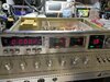
Cobra 2000 gtl counter issue
- Thread starter kaos513
- Start date

Looks like maybe a few folks have already tried to fix it.
As in "try" not "succeed".
Does changing modes from AM to sideband alter the display, or does it remain all zeroes no matter what you do?
Does pushing the "time" button change anything?
The only way I know to zero in on what parts of the counter display are alive, and which ones are dead is with a decent 50 MHz or better oscilloscope. This is not a gadget I know how to troubleshoot with a meter alone.
Maybe someone else knows how, but I don't.
Most-typical shutdown symptom for this counter would cause it to read "92.200" Mhz. The all-zeroes display is not a common symptom.
73
This thread mentions a counter stuck on 92.000:
https://www.worldwidedx.com/threads/cobra-2000-gtl-reads-92-0000.37105/
https://www.worldwidedx.com/threads/cobra-2000-gtl-reads-92-0000.37105/
The fix in the factory update adds a capacitor between pin 3 of IC501 and pin 1 of IC507. If yours is a later-production radio that part will have been installed at the factory, along with the resistors in the update.
Getting a peak from the slug in L501 is vitally important. Trouble is, you can't use the S-meter or wattmeter to observe the peak. A 'scope on pin 3 of IC501 is what I recommend. Honestly don't know another way.
Biggest thing to watch out for is the physical position of the slug where it peaks. If the slug is DEAD EVEN with the rim of the hole, this is a bad sign. Tells you the internal capacitor in that can has failed.
But until you see where that slug peaks, that's just speculation. No need to borrow trouble before it arrives.
One other thing we see is blown JFETs FET501 and/or 502. Tends to happen when the 4-pin plug on the side of the counter module gets unplugged or plugged in with the AC power cord connected. Runs the risk of a brief "reverse voltage" spike to either FET. Naturally, a 'scope will immediately reveal if either FET is not amplifying its input signal.
Never diddle that 4-pin plug on the side without first pulling the AC cord out of the wall. You'll never guess how I learned that.
73
dxChat
- No one is chatting at the moment.