• You can now help support WorldwideDX when you shop on Amazon at no additional cost to you! Simply follow this Shop on Amazon link first and a portion of any purchase is sent to WorldwideDX to help with site costs.

Cobra 2000 No voltage at Test points 7 and 8

Brian G

Active Member
Dec 21, 2020
313
33
28
56
There is no voltage at TP 7/8 posts. So therefore no voltage at final or driver.
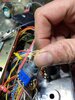
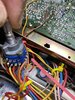
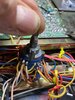
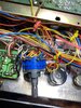
Trying to figure out where the disconnect is. Where does that 13 volts originate? Looks like maybe comes from mode switch? There is 13 volts at the white wire post on the switch per the schematics. The orange wire from the mode switch looks to be the feed to the test points. And there is the same (basically none) voltage at that post on the switch as there is at the test points.
Please guide me to where to look! I have schematic/Sam’s facts but I’m leaning towards the switch. Which will suck because there’s no way I’m gonna find a replacement for that without a scrapped radio which I don’t have.
 
Last edited:

Well.... if the switch has 13.8 on the LSb/USB pins and you put the switch in either of those positions and don't have 13.8 on the orange wired pin..... it does have a problem.

It looks like the white wire goes to the USB pin, then a green wire takes it over to the SSB pin and a red wire lands on the AM pin.... if you rotate that switch through all positions and get nothing on the orange..... that pretty much says it....

[edited to add]
a remote possibility..... something along the orange wire is pulling the voltage to ground/shorting it out.

If you can get the orange wire off of the switch and measure the pin on the switch it came from......
if voltage is back up....something out there is pulling it down.

That could be the driver or final but that same circuit trace (#145) sneaks over to the Modulation Meter circuit so don't forget to look that way as well. Although.....being an almost direct 13.8 v line...I would expect to see toasted parts in that area....

Just giving some ideas.....
 
Last edited:
Thanks
Well.... if the switch has 13.8 on the LSb/USB pins and you put the switch in either of those positions and don't have 13.8 on the orange wired pin..... it does have a problem.

It looks like the white wire goes to the USB pin, then a green wire takes it over to the SSB pin and a red wire lands on the AM pin.... if you rotate that switch through all positions and get nothing on the orange..... that pretty much says it....

[edited to add]
a remote possibility..... something along the orange wire is pulling the voltage to ground/shorting it out.

If you can get the orange wire off of the switch and measure the pin on the switch it came from......
if voltage is back up....something out there is pulling it down.

That could be the driver or final but that same circuit trace (#145) sneaks over to the Modulation Meter circuit so don't forget to look that way as well. Although.....being an almost direct 13.8 v line...I would expect to see toasted parts in that area....

Just giving some ideas.....
Thanks I will check it out. I did try checking it while operating the switch and there was still nothing but I’ll try pulling the wire off too and checking again.
 
Brian, if you want to call me nuts... that is fine with me!
I don't think I was right on the 4 pole 3 pos judgement. hear me out.....

I have made my EYES bleed going over the Cobra 2000 schematic in the Sams CB-251.

The mode switch is S403. Here is what I have found.....

S403-1 pin 9 in feeds pins 5,7,8 for the AM/SSB Signal Meter Ckt (CT # 102)
S403-3 pin 4 in feeds pins 1,2,3 for LSB/AM/USB Lamp selection (Ckt 26)
S403-4 pin 18 in feeds 14,16,17 for Driver/Final/Mod Meter (Ckt 145)
S403-5 pin 9 in feeds pins 5,7,8 for Power Supply SSB vs AM voltages (Ckts 3-7)

Now two things look wrong with this.

Both S403-1 AND S403-5 claim pin 9 feeding 5,7,8

and

There isn't a S403-2.

I have looked and looked an can't find ANYTHING calling out S403-2

Can you take a good look at that mode switch and answer TWO questions......

1) is it a SINGLE deck switch? Or is it TWO?
(the view they show in the Sams only shows FOUR 3 position switches from the rear view BUT Having 403-1 through 403-5 would IMPLY that there are MORE than 4 switches on the thing....but they could ONLY do that if there are multiple DECKS ... OR they are using boTH SIDES of ONE deck.)

2) look closely at that switch and see if it looks like there is ONE switch section that does not have anything soldered to it!!

I will be honest... I have never seen the inside of one of those ...... so I am just using my imagination....

But if that switch uses TWO decks(or two sides of the one!) and is the radio is not using 403-2..... you may have a spare section that you could rewire and use....

Fingers crossed.....


(and AS ALWAYS...if anyone out there knows better..... I would LOVE to be shot down out of the sky!!!!!! :) )
 
It is a 2 deck switch. But I will have to look at it again in regards to your other questions- it does have quite a few wires running to it.. If I can I will take a pic and post it if I can get a good view without unmounting it from the radio.
 
  • Like
Reactions: guitar_199
Yeah. If you can ....get in close and from several angles.... as many as you can.

I could certainly be missing it....but I have scanned that schematic (by eye)at least three times and I can not find any callout using S403-2... and that just seems weird. Usually....these folks aren't known for putting a single thing in that they don't have to....but the fact that they specify -1 through -5 but don't use -2.... well..... it has my attention!!!!

It is a 2 deck switch. But I will have to look at it again in regards to your other questions- it does have quite a few wires running to it.. If I can I will take a pic and post it if I can get a good view without unmounting it from the radio.
 
Yeah. If you can ....get in close and from several angles.... as many as you can.

I could certainly be missing it....but I have scanned that schematic (by eye)at least three times and I can not find any callout using S403-2... and that just seems weird. Usually....these folks aren't known for putting a single thing in that they don't have to....but the fact that they specify -1 through -5 but don't use -2.... well..... it has my attention!!!!
here are some pics. I took it out of the radio to see it. Looks like there are wires on both decks.
 

Attachments

  • 90FACF83-AFA2-4D3F-A36F-B526086A91F1.jpeg
    90FACF83-AFA2-4D3F-A36F-B526086A91F1.jpeg
    1.4 MB · Views: 15
  • 98DF36E7-C716-418F-AE7D-9F91481411E5.jpeg
    98DF36E7-C716-418F-AE7D-9F91481411E5.jpeg
    1.5 MB · Views: 15
  • F4985313-DFA0-4BC0-B370-20D3E6AB6C71.jpeg
    F4985313-DFA0-4BC0-B370-20D3E6AB6C71.jpeg
    1.4 MB · Views: 12
  • DA589FF8-00FE-4712-B99B-C626958CD399.jpeg
    DA589FF8-00FE-4712-B99B-C626958CD399.jpeg
    1.5 MB · Views: 13
  • 55AB7A06-7C96-4EFD-A524-3AC19023BC9D.jpeg
    55AB7A06-7C96-4EFD-A524-3AC19023BC9D.jpeg
    1.4 MB · Views: 13
AND in ALL FOUR PICS I see enough un-used pins to tell me that there MAY even be two sections on that switch that are NOT used.

I have a great suspicion that if you had an ohm meter....or a buzzer.....
and could figure out which empty pins make up a set..... you could move the wires off of the current orange red white (power to the finals) switch...... to one of the empties...and it would work.

As I say, I would ohm things out....or ring them with a buzzer......

But if that switch section is INDEED BAD...... I believe that you have a spare RIGHT THERE on that switch.

What do you think?
I have my ohm meter. How do I test those exactly? I can try it.
 
The toughest part is .....each set is four pins...... think of it as ONE goes in....but only goes to ONE of the others at a time....depending on which of the three positions it is in.

Is there any way that you could zoom in on a close picture....of the white,red,green with orange out.... the one that feeds the driver /final.... the one that you are having trouble with......

BY THE WAY.... I am making an assumption that I understand something....

Lets see if I do.

On THAT SECTION ... the one that has the orange wire..... out....
The terminal that has the white wire DOES have 13.8V
The terminal that has the green wire DOES have 13.8V
And The terminal that has the red wire DOES have something on it... less than 13.8V...maybe 8 ish or so.....

AND YET..... NO MATTER what position the switch is in......

you get NOTHING on the terminal with the orange wire.....

is all of that correct?
all correct.
 
Put the mode switch in the AM mode. Trace the ORANGE wire connected to TPs 7&8 back to the mode switch. The three other terminals in the set of 4 where the orange is connected are WHITE, RED, and GREEN. The wires you're concerned with are the RED and the ORANGE. The red wire brings voltage from the AM regulator (TR41) and there should be approx 8VDC on the red wire. If not, put the switch in either USB or LSB and check again. If still no voltage, there is a problem with the AM regulator. If the voltage is there on the red wire, with the switch in the AM mode, check the ORANGE wire for 8VDC. No voltage ... bad switch. Voltage ok ... open connection between the switch and TPs 7 & 8.

- 399
 
  • Like
Reactions: Shadetree Mechanic

dxChat
Help Users
  • No one is chatting at the moment.
  • @ Wildcat27:
    Hello I have a old school 2950 receives great on all modes and transmits great on AM but no transmit on SSB. Does anyone have any idea?
  • @ ButtFuzz:
    Good evening from Sunny Salem! What’s shaking?
  • dxBot:
    63Sprint has left the room.