• You can now help support WorldwideDX when you shop on Amazon at no additional cost to you! Simply follow this Shop on Amazon link first and a portion of any purchase is sent to WorldwideDX to help with site costs.

Cobra 2000 ssb tx dying out after a few minutes use . Am is fine

To demonstrate...

Here's a Cobra 142 GTL boards values for the AN612...

upload_2020-3-12_18-7-8.png

Pin 3 still uses IF from an amplifier TR22 in a similar way, but notice the VALUES used - they are different.

This goes on and on in the different radios and boards used in them.

In some ways you are chasing rainbows when it comes to direct sub approach - they change the values thru the years and you may not always achieve the results you want...

So lets also take another approach - you have to look at why they "terminate" a signal or "restrict" a signal in specific ways.

Some are because of Harmonics, others are due to Drive Levels - too much Drive makes harmonics, too little signal amplified GREATLY can produce the same results because there is not enough of one signal to mix in proper ratios to the other. When the board can't amplify the signals the right way - you get skewed results.

You may need to expand your search - as SP5IT eluded to, you'll need to locate other areas that can accept and deliver a signal - so that means you need to do some routine checking of parts thru the signal chain. It may be the original design they intended was to send a signal at a SPECIFIC strength to these sections - only due to minor (although that is used loosely) tweaks either at the coil output levels or the Semiconductors (like the AN612) produced in this run or lot - expected Engineered didn't meet Manufactured output levels and changes had to be made.
 

Attachments

  • upload_2020-3-12_18-3-37.png
    upload_2020-3-12_18-3-37.png
    341.4 KB · Views: 5
  • Like
Reactions: 357magnum
One last note on this ...

How is your Frequency Counter doing?

Is it working all the time...

When you lose signal in SSB does the Frequency counter go to 0 or still works?

Have you ever lost the Frequency counter signal - where the display went to blank or gave you an odd number in the display?

If the frequency counter is working - is it sucking all your signal into it - as in a termination problem?
 
  • Like
Reactions: 357magnum
I tell all my locals about this forum & the amazing members & info on here ! Some have joined some .... well they must know too much already ! :LOL: Not me ! I been doing this over 50 years & still learning . Thanks again all for the input ! 73 , Leo
 
Ok, we did make some progress, and I see with all those posts that perhaps we need to make a list...

Ok...
  • Tested - looked for Signal out on Pin 7 of AN612
    • What was your result - BEFORE and After SSB dies?
  • Removed TR21 to verify that TR31 switching matrix was ok - was able to recreate problem with TR21 removed - solved several steps - this appears to not involve the Mic amp, or PA amp...
  • We will need to check LIMITER TR24 - remove to see if SSB dies again...verifies AMC/ALC are ok
  • Test and scope Pin 3 of AN612 - we need to see if we are sending TOO much signal or too weak of signal from TR32
  • Check Frequency Counter Signal - does FC work during this entire phase of both SSB ok and then dying?
Now with the above steps...

Afterwards we need to look for FT3's status, not necessarily the "block" itself, just the input and output - there are a series of events that happen when in SSB modes, versus AM modes and also during RX/TX switching - for the FT3 serves to provide several functions and not unlike the PLL does play a major role in how the radio encodes (Pin 7 AN612) and decodes (TP3/TP4) SSB signals as well as provide a balancing effort to mix signals from two IF sections to make the 27MHz possible at IC5.
 
  • Like
Reactions: 357magnum
Don't worry, if you knew what I go thru here everyday at the home-20' - this stuff is a blessing...

It's a passion I have for Radio, that got developed when I was younger.

Not just it's "electronics" - but due to the friendships it has made throughout the years.

Many have gone silent key, so that knowledge is gone - lost forever.

So in a way I'm the legacy others have instilled in me their hopes and dreams, their efforts of leaning radio to continue as a hobby, and as a tool - to learn what you never knew to know now - and to meet people you never knew you now know.
 
  • Like
Reactions: 357magnum
Good evening, well Andy all i will say is your a genius and thank you for sharing your knowledge. I think the way you explain things is magic.
For me i remember my father in the early 1960s , he used to trick around in the old valve radios, i used to be fascinated watching him. He never studied electronics or anything like that but he gave me the bug. I would love to have better understanding of how these radios work.
ANyway today i checked out various resistors around the 7.8 all appear ok i changed
capacitor c98 and c68.
I checked the an612 pin 3 about 100mv 7.8 and pin 7 i see modulation on it when i speak into the mike,
changing from upper to lower sideband switches the frequency slightly up and down so that sounds ok.
I also removed tr24, this made a big difference so now i am letting it run and see what happens later.
Everything over here has come to a standstill with the corona virus, we are all isolating for a while I hope that you and your families are safe.
jimmy
 
  • Like
Reactions: 357magnum
  • Same here from us to you too...

But was wondering if and when this is all said and done if TR24 was a Symptom that underlies the culprit and we just have to figure out how to make the ALC part of this, when you're in SSB mode, to work correctly again.

It was when you said 2 watts, that tells me that the ALC adjustment may have been TOO Tight and so it affects the Limiter by "clamping" and since it's a bit sensitive (2 watts is pretty low power) it may remain clamped...OR we had a problem with the Input to the AN612 - you ruled those out when you said TR21 was fine and that AM seemed to recover and work - a side clue was - you sounded kinda rough (to put it fewer words) in SSB mode - so from the previous repair until now, to see if ALC was adjusted too tightly - would make far better sense.
  • Shame on you Andy...:censored::notworthy::confused::oops:
However, the opposite can be true too, like how much of one signal was being applied to another - and if it can't meet in the middle - a part of this mixer (Balanced Modulator AN612) shuts down and you lose half your signal. And when that happens, everything disappears - this this case I was referring to the Pin 3 and Pin 1 signal mixing that needs to happen - if the mixing wasn't balanced - you may cause a shut down inside the part to protect itself from too much signal being applied and overheating. That was where I was heading - was to determine if you have a bad cap...or if your signal from TR32 was not up to snuff...
  • SP5IT deserves the credit for this - he was asking about Pin 7 - if you even had any output - which made me ask if you even had the Frequency Counter working thru all of this event
  • - because of the IF-signal from TR32 as a Frequency the Frequency counter looked for being applied at Pin 3 should have some output
  • - at Pin 7, of AN612 - it would also have been affected. But as showing frequency "bouncing" all over the place and you couldn't get a steady reading of the channel frequency you were on.
  • FT3 remember, takes the EXPECTED signal you chose thru Mode and removes the other half of the Sidebands' as well as selected narrow Carrier signal itself when you use the SSB modes.
  • You got a frequency because the Balanced Modulator CENTERED on a frequency - which produced a carrier so the Frequency Counter saw something all the time
  • - your FT3 would have trimmed off everything else and IC5 would have seen - leaving just your Selected SSB mode MINUS the OFFSET - which the PLL then ADDED in Frequency (that 2nd component of it's own IF) to compensate that loss - which when both IF signals are combined at IC5 - gives you 27MHz output of the channel you're on and the TX strip simply amplifies that.

Since you had the radio in front of you - I can only guess by looking over your shoulder - what you were seeing thru this forum...

Only time will tell...
 
  • Like
Reactions: 357magnum
thanks Andy, son far so good the radio is still working this is the longest it has operated since we began the adventure. THe power is back up and the audio is fine.
I think it will live again.
So tr24 is checking out ok so something associated with its circuit could be the problem.
I think you have remote vision.:)
 
Just so you know, we may not be done with this...

thanks Andy, son far so good the radio is still working this is the longest it has operated since we began the adventure. THe power is back up and the audio is fine.
I think it will live again.
So tr24 is checking out ok so something associated with its circuit could be the problem.
I think you have remote vision.:)
No, just intuition...

I've seen my share of fun chassis' like what were doing here on-line... and the efforts others have done to them - that was one job I just recently had that I gave up - no money in it - just cleaning up the mess. My former boss got all the Glory - I got all the dirt...

Ok, why I'm thinking what I'm thinking...

I'll leave this with you...
Cobra2000AudioALCAMCConfig.jpg

Take you time with this...there's more to add in the future...

Right now this is how that Audio path works.

IF you're having issues with low-audio levels in a TYPE of mode, this radio provides two - AM and SSB - but one uses carrier with the Audio in an Envelope around it in Modulation - in AMPLITUDE. While another uses just the Audio in a portion of the AM mode - it's Sideband - the Modulation Amplitude portion of the AM Signals an AM Transmitter makes..

TR24 is important that is provides a means to control the level of audio signal so you are not over modulating your Microphone and generating more unintelligible distortion than you're making in Audio signal - you want to be heard right? Then the Limiter - in it's function - will keep your audio levels to within acceptable limits so you don't over modulate or otherwise distort your audio making you unable to be copied when others are listening.

You can lose an audience far quicker using over modulated and distorted audio signal - it easier to lose them than to have a less than full modulated signal - at least they can turn the volume up to hear you on the latter condition.

TR24 is part of an amplifier array of parts that take the samples of signal from other sections that are amplifying your audio and / or TX signal and then processing them into a control signal that allows the limiter to simply limit your voice peaks but let your less volume weaker softer sounds and inflections of your voice pass thru without compromise.

One is Called Audio Modulation Control - AMC - a circuit used to keep Modulation Envelope from expanding too far into other channels next to the Frequency your AM Transmitter is on.
  • It uses the AM Regulator that imposes Audio onto a DC voltage making it swing above and below the DC voltage - this is applied to the Final and Driver in the Transmitter portion of the Radio - this makes an AM signal - a Carrier (your DC power) and an Envelope (your Audio signal amplified into a Modulated signal). In AM signal that is transmitted by this radio, you generate a Carrier with two sets of Audio information. - IF you remember your Mathematics - when you mix two frequencies - you get a set or groups of frequencies - right? So, when you add an audio signal to a simple AM carrier frequency - you are making two more frequencies along with your Carrier.
  • Carrier frequency doesn't change, but the Audio added to it ADDS more frequencies as a range of Audio around it. So if you have say a 450Hz tone - to your 27,000,000Hz (or 27MHz) you have 27,000,450Hz AND 26,999,550Hz in Audio information contained around your carrier - they are the mixing products of the added Audio signal - both above and below you Center frequency as added information
The Other One is Audio Limiter Control - or ALC and is for the SSB signals generated in the TX side of the radio.
  • It uses the Audio Information - a set range of Frequencies next to the Carrier Frequency of the Channel you are using.
  • USB or Upper Side Band is a range of frequencies just above the Carrier Frequency - in frequency. It's your Modulated Audio Signal range of frequencies ADDED to your Carrier so that when you decode the information - all you hear is the audio information contained in that range of Frequencies ABOVE the Carrier Frequency.
  • LSB - Lower Side Band is to the other side of the Carrier Frequency - the lower range of Frequencies that have your Audio Modulation signal that are the SUBTRACTED band of frequencies or the mirrored - inverted - range of Audio Frequencies starting just BELOW Carrier Frequency - that are just like that of the Upper Side Band Range of Frequencies - only they are below the Center frequency - or CARRIER Frequency.
upload_2020-3-13_22-30-18.png
Both work SEPARATELY - but go into a Modulation Amp (MOD Amp) that process' the signals - since they are "samples" of signals generated when you talk into your microphone and changed over to an Audio signal - you can think of this as a Feedback principle - A means in which to control the dynamics your voice imposes in force - or Volume from your voice - so the radio works within a range of parameters it has to as set by the FCC.

I had to tell you the above so you'd be able to understand what I'm meant by not being quite done...

TR24 is the Limiter - and it plays a more important role than many people think.

Sure it limits audio - but there is more to this story than just Loud audio and the prevention of it. It also is used to SILENCE the Microphone Amplifier inside the radio - so it's not producing more noise into the receivers' lines that the Radio already is sending to the Audio amp from its receiver section.

Yes, See Diodes D59 and D60 above in the Graphic, By TR24? They steer power to and From the Limiter - for the purposes of opening the Mic Audio line only when needed.

When the radio is receiving - the RX line sends power to the Limiter. RX Mode - turning it on, thru D59 - and puts the Mic Line thru TR24 into ground. Like a shunt - this helps to keep any noise or buzz, static or even other noisy electrical interference from adding to the noise level in the receiver - well it's not in the receiver - but it's mixing in with what ever else the receiver is picking up and putting it into the Audio Amp chip at the same time your radios' receiver is trying to receive.

D60? Note where it is at, it serves as a means to TURN OFF the Limiter when you are in PA mode. This way your PA system can operate normally.

Why is this such an important condition? Well, the Mic Amp strip shown above is ON - ALL THE TIME when the power is on. So you'll need the Limiter as well as the CB PA switch working correctly so your radio can receive weaker signals, that if these parts had not been in there, can drown out your ability to hear and discern the signals your receiver is trying to amplify so you can hear them thru the speaker.

So what does this mean?

Well I did ask a lot of questions about your PA/CB switch and if it was working ok. For if not, this can force a condition where the Mic Amp is routed to a Monitor Tap and nothing else can take place because the PA amp is trying to send power thru it into the Audio AMP side, but since you're in SSB more - TR21 (not shown) is shunting Audio to the Audio Amp but the Audio amp is MUTED because you're in SSB mode, not AM.
  • You can also look at this in a standpoint of a DPDT switch - which on many CB's is used for Togglnig CB PA functions.
  • It needs to serve two functions.
  • Reroute Speaker audio to PA speaker.
  • Forces TX mode to stop so your radio only sends audio thru that PA speaker jack.
If one or the other condition is not properly met, the radio can think it's in TX but the PA system thinks it's on instead
  • - now you have a device contention and the radio doesn't seem to work.
  • You say AM is fine - and so it would seem.
  • Why? Because ALL the Mic Amp audio goes thru to the Audio Amp PA Mode AND IN CB. In SSB modes though - the radio thinking it's in one mode will try to send audio into the AN612, but if TR21 is thinking it's in SSB, what does the PA amp do or what is the Audio Amp doing?
Audio Amp in SSB mode is MUTED in TX, so the symptoms of what you said it did, can satisfy that condition of yes, that can cause this.

So taking out TR21 and the radios' SSB mode still died - then that removes that part as suspect - it's was the most effective way to think this thru...
  • Now by removing TR24, we removed a limiter but it cleared up the condition
    • - so as a part of this problem - it is not yet fixed,
    • - but the radio is operable in the two modes.
  • IF you are fine with this then operate the radio as you see fit.
  • IF you are not ok with this - I'd be more than happy to try and help you sort this out.
So, if TR24 needs to work, then make it so. (Number One - :) ) and that also means that this condition may occur again, so we will have to keep an eye on this as you work out the ALC and AMC control issues TR24 needs to have to make the radio work normally again.
 
Last edited:
Just so you know, we may not be done with this...


No, just intuition...

I've seen my share of fun chassis' like what were doing here on-line... and the efforts others have done to them - that was one job I just recently had that I gave up - no money in it - just cleaning up the mess. My former boss got all the Glory - I got all the dirt...

Ok, why I'm thinking what I'm thinking...

I'll leave this with you...
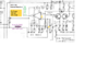
View attachment 35184

Take you time with this...there's more to add in the future...

Right now this is how that Audio path works.

IF you're having issues with low-audio levels in a TYPE of mode, this radio provides two - AM and SSB - but one uses carrier with the Audio in an Envelope around it in Modulation - in AMPLITUDE. While another uses just the Audio in a portion of the AM mode - it's Sideband - the Modulation Amplitude portion of the AM Signals an AM Transmitter makes..

TR24 is important that is provides a means to control the level of audio signal so you are not over modulating your Microphone and generating more unintelligible distortion than you're making in Audio signal - you want to be heard right? Then the Limiter - in it's function - will keep your audio levels to within acceptable limits so you don't over modulate or otherwise distort your audio making you unable to be copied when others are listening.

You can lose an audience far quicker using over modulated and distorted audio signal - it easier to lose them than to have a less than full modulated signal - at least they can turn the volume up to hear you on the latter condition.

TR24 is part of an amplifier array of parts that take the samples of signal from other sections that are amplifying your audio and / or TX signal and then processing them into a control signal that allows the limiter to simply limit your voice peaks but let your less volume weaker softer sounds and inflections of your voice pass thru without compromise.

One is Called Audio Modulation Control - AMC - a circuit used to keep Modulation Envelope from expanding too far into other channels next to the Frequency your AM Transmitter is on.
  • It uses the AM Regulator that imposes Audio onto a DC voltage making it swing above and below the DC voltage - this is applied to the Final and Driver in the Transmitter portion of the Radio - this makes an AM signal - a Carrier (your DC power) and an Envelope (your Audio signal amplified into a Modulated signal). In AM signal that is transmitted by this radio, you generate a Carrier with two sets of Audio information. - IF you remember your Mathematics - when you mix two frequencies - you get a set or groups of frequencies - right? So, when you add an audio signal to a simple AM carrier frequency - you are making two more frequencies along with your Carrier.
  • Carrier frequency doesn't change, but the Audio added to it ADDS more frequencies as a range of Audio around it. So if you have say a 450Hz tone - to your 27,000,000Hz (or 27MHz) you have 27,000,450Hz AND 26,999,550Hz in Audio information contained around your carrier - they are the mixing products of the added Audio signal - both above and below you Center frequency as added information
The Other One is Audio Limiter Control - or ALC and is for the SSB signals generated in the TX side of the radio.
  • It uses the Audio Information - a set range of Frequencies next to the Carrier Frequency of the Channel you are using.
  • USB or Upper Side Band is a range of frequencies just above the Carrier Frequency - in frequency. It's your Modulated Audio Signal range of frequencies ADDED to your Carrier so that when you decode the information - all you hear is the audio information contained in that range of Frequencies ABOVE the Carrier Frequency.
  • LSB - Lower Side Band is to the other side of the Carrier Frequency - the lower range of Frequencies that have your Audio Modulation signal that are the SUBTRACTED band of frequencies or the mirrored - inverted - range of Audio Frequencies starting just BELOW Carrier Frequency - that are just like that of the Upper Side Band Range of Frequencies - only they are below the Center frequency - or CARRIER Frequency.
Both work SEPARATELY - but go into a Modulation Amp (MOD Amp) that process' the signals - since they are "samples" of signals generated when you talk into your microphone and changed over to an Audio signal - you can think of this as a Feedback principle - A means in which to control the dynamics your voice imposes in force - or Volume from your voice - so the radio works within a range of parameters it has to as set by the FCC.

I had to tell you the above so you'd be able to understand what I'm meant by not being quite done...

TR24 is the Limiter - and it plays a more important role than many people think.

Sure it limits audio - but there is more to this story than just Loud audio and the prevention of it. It also is used to SILENCE the Microphone Amplifier inside the radio - so it's not producing more noise into the receivers' lines that the Radio already is sending to the Audio amp from its receiver section.

Yes, See Diodes D59 and D60 above in the Graphic, By TR24? They steer power to and From the Limiter - for the purposes of opening the Mic Audio line only when needed.

When the radio is receiving - the RX line sends power to the Limiter. RX Mode - turning it on, thru D59 - and puts the Mic Line thru TR24 into ground. Like a shunt - this helps to keep any noise or buzz, static or even other noisy electrical interference from adding to the noise level in the receiver - well it's not in the receiver - but it's mixing in with what ever else the receiver is picking up and putting it into the Audio Amp chip at the same time your radios' receiver is trying to receive.

D60? Note where it is at, it serves as a means to TURN OFF the Limiter when you are in PA mode. This way your PA system can operate normally.

Why is this such an important condition? Well, the Mic Amp strip shown above is ON - ALL THE TIME when the power is on. So you'll need the Limiter as well as the CB PA switch working correctly so your radio can receive weaker signals, that if these parts had not been in there, can drown out your ability to hear and discern the signals your receiver is trying to amplify so you can hear them thru the speaker.

So what does this mean?

Well I did ask a lot of questions about your PA/CB switch and if it was working ok. For if not, this can force a condition where the Mic Amp is routed to a Monitor Tap and nothing else can take place because the PA amp is trying to send power thru it into the Audio AMP side, but since you're in SSB more - TR21 (not shown) is shunting Audio to the Audio Amp but the Audio amp is MUTED because you're in SSB mode, not AM.
  • You can also look at this in a standpoint of a DPDT switch - which on many CB's is used for Togglnig CB PA functions.
  • It needs to serve two functions.
  • Reroute Speaker audio to PA speaker.
  • Forces TX mode to stop so your radio only sends audio thru that PA speaker jack.
If one or the other condition is not properly met, the radio can think it's in TX but the PA system thinks it's on instead
  • - now you have a device contention and the radio doesn't seem to work.
  • You say AM is fine - and so it would seem.
  • Why? Because ALL the Mic Amp audio goes thru to the Audio Amp PA Mode AND IN CB. In SSB modes though - the radio thinking it's in one mode will try to send audio into the AN612, but if TR21 is thinking it's in SSB, what does the PA amp do or what is the Audio Amp doing?
Audio Amp in SSB mode is MUTED in TX, so the symptoms of what you said it did, can satisfy that condition of yes, that can cause this.

So taking out TR21 and the radios' SSB mode still died - then that removes that part as suspect - it's was the most effective way to think this thru...
  • Now by removing TR24, we removed a limiter but it cleared up the condition
    • - so as a part of this problem - it is not yet fixed,
    • - but the radio is operable in the two modes.
  • IF you are fine with this then operate the radio as you see fit.
  • IF you are not ok with this - I'd be more than happy to try and help you sort this out.
So, if TR24 needs to work, then make it so. (Number One - :) ) and that also means that this condition may occur again, so we will have to keep an eye on this as you work out the ALC and AMC control issues TR24 needs to have to make the radio work normally again.[/QUOTE

Thank you again. For that description of the audio circuits. It gives me a better understanding of where we are now..
So I wish to continue to to trace this problem for a few reasons
1....further broaden my understanding of the cb radio
2..to help others who I'm sure like me find it fascinating logic.
3 to get the radio operational as it was.

So If your free I am most greatful of your help
J
Ok so the radio is still working today
 
  • Like
Reactions: 357magnum
upload_2020-3-14_9-40-7.png


Thank you again. For that description of the audio circuits. It gives me a better understanding of where we are now..
So I wish to continue to to trace this problem for a few reasons
1....further broaden my understanding of the cb radio
2..to help others who I'm sure like me find it fascinating logic.
3 to get the radio operational as it was.

So If your free I am most greatful of your help
J
Ok so the radio is still working today

Sorry it was so long but it's hard to simply show and then tell...
 
  • Like
Reactions: 357magnum

dxChat
Help Users
  • No one is chatting at the moment.