Yes i am having a weird issue with my squelch when i turn it all the way to the left it silence's the audio completly even with a +30db signal, when i turn it to the right the audio comes back. So the squelch is not working and its backwards. Any help would be awsome. Also I cannot set the bias on the final for some reason no mA reading at all on the meter when i try. I have done the NPC mod on the radio if that helps.

You are using an out of date browser. It may not display this or other websites correctly.
You should upgrade or use an alternative browser.
You should upgrade or use an alternative browser.
-
You can now help support WorldwideDX when you shop on Amazon at no additional cost to you! Simply follow this Shop on Amazon link first and a portion of any purchase is sent to WorldwideDX to help with site costs.
Cobra 2000GTL Squelch Issue
- Thread starter 88_bandit
- Start date
My guess would be that the potentiometer was replaced and wired incorrectly. It should be a simple fix to move the outboard wire to the opposite outboard terminal on the potentiometer and that should correct your issue.Yes i am having a weird issue with my squelch when i turn it all the way to the left it silence's the audio completly even with a +30db signal, when i turn it to the right the audio comes back. So the squelch is not working and its backwards. Any help would be awsome. Also I cannot set the bias on the final for some reason no mA reading at all on the meter when i try. I have done the NPC mod on the radio if that helps.
Actually the squelch was working properly before I went to set the bias the other night and then it started doing what I said before and yes I am doing the bias just the way the Sam’s book tells me to do it I can set the driver just fine but when I go to set the final I get no reading. I do them one at a time is that the correct way to do it or do I unplug both of them at the same time
One common failure I have seen that prevents getting a bias reading on the final transistor is C153, a 47uf 10-Volt electrolytic cap. It's on the "Ten-Volt Blues" list of caps that tend to fail first after 30, 40 years or more. When it fails as a short, no voltage can reach the base of the final transistor when the trimpot is turned. Result is no idle current.
The backwards squelch control is a much bigger puzzle. Shouldn't be possible for it to do this. First thing I would want to know is if the RF Gain control appears to function as it should. The squelch is opened and closed by AGC voltage. If this circuit has a fault, it may also affect how the RF Gain control behaves.
Maybe.
Was any work of any kind done on this circuit board? The backwards squelch sounds more like a solder blob that fell onto the circuit board and bridged two separate circuits together.
73
Yes the RF gain works the way it should, I was trying to set the bias and may have slipped and touched something With the meter leadsOne common failure I have seen that prevents getting a bias reading on the final transistor is C153, a 47uf 10-Volt electrolytic cap. It's on the "Ten-Volt Blues" list of caps that tend to fail first after 30, 40 years or more. When it fails as a short, no voltage can reach the base of the final transistor when the trimpot is turned. Result is no idle current.
The backwards squelch control is a much bigger puzzle. Shouldn't be possible for it to do this. First thing I would want to know is if the RF Gain control appears to function as it should. The squelch is opened and closed by AGC voltage. If this circuit has a fault, it may also affect how the RF Gain control behaves.
Maybe.
Was any work of any kind done on this circuit board? The backwards squelch sounds more like a solder blob that fell onto the circuit board and bridged two separate circuits together.
73

You need to check the potentiometer - the mess made during the "tune" may have applied FULL voltage thru the wiper arm of the pot - or pure ground - which blows the pot open like a fuse when it comes to continuity.
The Squelch control works by applying a "fixed known voltage" that is "weighted" by the signal strength in the AGC section.
The power supply to the control being fixed, is buffered - and the signals strength is summed in with the squelch "threshold" so the system - when it receives a strong signal onto a marginal one above the noise level - the squelch opens allows you to hear the call - the variable is the threshold control - the AGC adds or takes away power the squelch system has in control over its ability to silence the audio.
So, since the control is now opposite - this tells me the pot has opened up
You need to check the potentiometer - the mess made during the "tune" may have applied FULL voltage thru the wiper arm of the pot - or pure ground - which blows the pot open like a fuse when it comes to continuity.
The Squelch control works by applying a "fixed known voltage" that is "weighted" by the signal strength in the AGC section.
The power supply to the control being fixed, is buffered - and the signals strength is summed in with the squelch "threshold" so the system - when it receives a strong signal onto a marginal one above the noise level - the squelch opens allows you to hear the call - the variable is the threshold control - the AGC adds or takes away power the squelch system has in control over its ability to silence the audio.
So, since the control is now opposite - this tells me the pot has opened up
disconnect the wires from the pot using an ohm meter and turn pot while looking at the meter it will show open or adjustableHow would I check to see if it is bad?

Set the control to mid-point.
Unsolder all the pots wires from the pot - either from the board, remembering where they go, or at the pot itself - since it's mounted - removing a combination usually a combination of one wire here (on mainboard) and two there (on control) as an example - might help more.
Using a DVM - set to 20K or 200K test two terminals - does an ohmic result show?
Do, the same thing with one terminal being the SAME and testing the other side - do you get an ohmic result?
Now, remember that SAME terminal? Don't use it for this last test - test the other two terminals.
If all terminals show ohmic results - use the lowest ohmic setting to test without it showing OL or 1.000 (no result or ohmic too high to obtain a result from that multiplier setting of the DVM)
IF all show ohmic, is your DVM on the lowest multiplier setting it can be for testing the ohmic structure and substrate?
Rotate the knob to change the position of the wiper arm - then retest - now you can develop an idea of which leg of the pot is the wiper arm variable.
Example, a 50K pot, and a 20K setting on the DVM - it will show OL - which can give you a "bad result" (open line or out of range) So remember to set the DVM to the best multiplier range to test the ohmic value of the pot - so in this case - the 200K setting is correct to use - you'll get results on all leg tests if the pot is structurally sound.
- You can get readings - but they are in error - even on a bad pot - you can be led to believe that part is still good because of the reading. So you'll need to remember the pot swipes from left to right - but if the pot opened up on one side - the swipe will still show - but as a VERY HIGH ohmic reading (above 500KΩ) so pay attention to the pots own ohmic rated / stamped on the back - usually a 103 means 10,000 or 10KΩ)
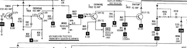
- In the schematic snipped above the pot is a 100Kb refers to LINEAR taper (B) and 100K Substrate - or 104.
- There is also the issue of reversed wiring - the Ground to the pot goes to a FIXED value terminal (where the two terminals have the same ohmic value no matter which way the wiper arm is turned) I've seen wiper arm go to ground in error - so be aware of reattaching wires - one - board ground is at a FIXED terminal - Wiper heads off BACK to the board - the power supply to the pot COMES from the board off of a 10K resistor.
IF the pot is open on one side - you can still make it work by reattaching the wires (usually two) and just reverse the wire color code to the two terminals that still show ohmic - just remember you may need to reverse the wire color code to those terminals.
In the above snippet - the 6.8K resistor connection also needs to be reversed to the other FIXED value terminal. (If you decide to keep the pot - knowing it will be reversed in operation - else just replace the pot keeping in mind the terminal layout - which two are fixed and one being the wiper)
Refer to your pic you took at step 1.
Last edited:
Any chance that someone reversed the two outside wires on the control?
73
73
dxChat
- No one is chatting at the moment.