• You can now help support WorldwideDX when you shop on Amazon at no additional cost to you! Simply follow this Shop on Amazon link first and a portion of any purchase is sent to WorldwideDX to help with site costs.

Cobra 2000gtl Unmod and Repair

Mustangtc65

New Member
May 31, 2026
3
2
3
44
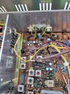
Hello, my name is Ty and I am here for guidance. Few weeks ago I purchased a very nice, ascetically, 200gtl. I am new to electronics, but I am learning and searching multiple forums. Everyday I read and reread threads and things are starting to make more sense. Currently I have a nice multi meter and soldering station. My 2000 has multiple mods. It has echo/talkback board, clarifier unlock, power mod, channel mod, and 4 pin mic. Luckily no wires were cut for the 4 pin mic mod. I was able to remove it and now have the correct 5 pin. there are many wires and components clipped. I have a page full of notes of issues that I see, but want to keep this first post short so not to get overwhelmed. The capacitors look to be original. All are Rubycon brand, light and dark blue. The radio receives great from what I can tell. The first issue I would like to correct, maybe multiple issues causing, is the radio has a constant tone/hum in AM only and the "On Air" light is always lit. It is audible through both speaker and phone jack. Does not increase or decrease with volume. It has a very low transmit. I am barely able to hear transmit on another radio only a few hundred feet away. When I key the mic there is no reading on the meter. Goes to flat 0. Speaking into the mic does move the meter normally. I have removed the echo and talkback board. The tone/hum was there before and after the removal of the board. I would like to remedy these two issues so that the radio is usable while i work through the others. I will do my best to answer questions and post photos the best I can.
Thanks, Ty
 
  • Like
Reactions: Gman and doffo

Um, receiving or transmitting? Or both?

73
Hum/tone goes away when keyed up. The TX "On Air" light is always on. When I key, the receive light goes out and the transmit light gets abit brighter. I was testing the voltages of the IC4 and I noticed TR37, close to the finals, is getting very hot. If the Rubycon capacitors are original i was thinking about getting a KlondikMike kit.

IC4 voltages
1-.99
2-0.0
3-8.32
4-13.74
5-.04 no change when keyed
6-8.31
7-13.75
8-8.31
Thanks, Ty
 
Since pin 2 is the input and pin 7 does nothing per the datasheet, I am going to guess that you have those pin numbers reversed.

Since the mounting tab would be away from the heat sync if installed backwards, I am going to assume it's not in backwards. Maybe check that just to be sure.

If it was just a case pin mis-labeling, recheck (the correct) pin 5 for changes when keying. Lets be sure that part works.

And before you do that, pull the jumpers from the finals so they are not working during this test because that hot bias transistor can (if it hasn't already) do damage to the finals. I assume any damage to the bias pot and diode would have occurred already. Cross that bridge when we get there.

What you should see is pin 5 and 6 go low and 8 go high when keyed. And pin 8 having 1v on it in RX makes me think a bad diode somewhere (or perhaps a bad transistor) is back feeding RX power into the TX side.
 
Last edited:
Since pin 2 is the input and pin 7 does nothing per the datasheet, I am going to guess that you have those pin numbers reversed.

Since the mounting tab would be away from the heat sync if installed backwards, I am going to assume it's not in backwards. Maybe check that just to be sure.

If it was just a case pin mis-labeling, recheck (the correct) pin 5 for changes when keying. Lets be sure that part works.

And before you do that, pull the jumpers from the finals so they are not working during this test because that hot bias transistor can (if it hasn't already) do damage to the finals. I assume any damage to the bias pot and diode would have occurred already. Cross that bridge when we get there.

What you should see is pin 5 and 6 go low and 8 go high when keyed. And pin 8 having 1v on it in RX makes me think a bad diode somewhere (or perhaps a bad transistor) is back feeding RX power into the TX side.
When I looked at the Factory service manual, is looked like the arrow was pointing at pin 1 towards the front of the case. Numbers reversed with keyed.
1-8.31
2-13.75
3-8.31
4-.04
5-13.75 keyed .10
6-8.32 keyed .27
7-0.0
8-.99 keyed 8.35
Looks like that would be correct with your explanation. By jumpers, do you mean the purple and yellow wires with the clear tube? If so the yellow wire is cut.

Thanks, Ty
 
Last edited:

dxChat
Help Users
  • No one is chatting at the moment.
  • @ COWBOYS:
    What can I do to make my Denton GLS 1000 amp to load ?
  • @ AudioShockwav:
    Try starting a new thread in the Amplifier section and asking the question, more people will see it to respond.
  • @ iw7ed:
    hello