I would rather fix it and know it was another success story. Just knowing I got it working is more satisfaction than can be imagined.

You are using an out of date browser. It may not display this or other websites correctly.
You should upgrade or use an alternative browser.
You should upgrade or use an alternative browser.
-
You can now help support WorldwideDX when you shop on Amazon at no additional cost to you! Simply follow this Shop on Amazon link first and a portion of any purchase is sent to WorldwideDX to help with site costs.
-
A Winner has been chosen for the 2026 July 4th Retevis RA89R Giveaway! Click Here to see who won!
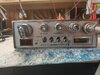
Cobra 25 LTD Classic, no voltage change tuning
- Thread starter Mark A Bradley
- Start date

Andy I understand your pain, trust me, at 40, after a fusion on my back, I had a full blown stroke. I had lost my whole right side, my face was drooping, I could not speak, still have right side weakness. OK, now in 2015, after a MRI, I was informed by the Physician reading the MRI, personally called me to tell me I had a canerous mass on my Spinal cord, get to the E.R. he tells me. Next thing I know I am having Radiation, then Chemo, talk about pain and sucking, not suffering. Now that was a long process, but after going to Rush university also to have Chemo injected into my Spinal Cord, making sure my brain did not contact any of the Cancerous Cells, now that hurt like hell, the needle had to be over 6 inches long to reach my Spinal Cord through the Disks, but the Surgeon had a Newbie Student doing the injection, and it made it easier for me that I had had a fusion and he was able to maneuver the needle through the hardware in the back and get it into the Spinal Cord watching it all on a screen that had a x-ray machine just above my back where he was wo0rking.There are things in this world that if we don't do something to redirect our efforts.
The pain keeps returning and will never leave, unless - until, we find a way....
You should try and take on someone else's pain...like mine - I've got a lifetime of suffering from it.
Now, you tell me you are going to be comfortable with a student, sticking a 6 inch needle in your back, into your spinal cord for the first time on anyone. I was not to happy with this B.S., I was totally freaking out on the operating table, they tried to tell me to settle down and stop moving, I was trying to get out of the straps and get the hell out of thereLOL. That was a scare for me. I know your pain sir, I deal with it every day, night, really bad getting up in the morning until the opiates kick in and try to knock the pain out, my I think I am immune to the stuff, over 20 years on Oxy, and Xanax for the pain. OK, I know this is a throw away radio, but I though since I started on it I would try my best to repair it, just a I am not going to give up mode. I will go over what you sent me, even if it takes me to early morning, and update in the late morning, Central time..Have a great nite,
Andy, about then Voltage,,I went ahead and replaced the D12, D18, D3, D20, D2,which I think it called for a 9.4 Volt, which I put in a IN4740A.Ok, broke this down into another step because you may need to look at something the Radio uses to determine it's "health"
PLL to make sure things are working - will be happy enough to send out stuff, but if one section isn't working - it designed to shut down - that's where Pin 4 comes into play.
The loop from the VCO is one thing, but it also needs to know signal is getting out, so it looks to two sense diodes - designed to detect, and rectify a small RF signal presence into a current (power) the PLL can see this and utilize it as a means to monitor it;s health and prevent unwarranted emissions - A.K.A. - out of lock and something's wrong stuff the engineers put in there...
So Pin 4 is ACTIVE when the PLL is working and RF is being used (also known as IF and RX - as well as TX stuff)
Those didoes are D12 and D18 - in the old '25s - you'd see power (about 7.5V max) all the time on Pin 4 of the PLL.
On pin 4, all I have is 00.185 Volts.That may be a issue, as it seems a bunch of resistors do not have any voltage at all, 0 volts on both ends of resistors.
Like R50, by the PLL, has 0 volts, and some have 8.00 Volts.And did I fail to mention the Red and Green TX RX light does not light up at all.
Hmmm.
Well, I know your new, remember that resistors have power flowing thru them - be careful!
The "voltages" are important to know, it's why some service manuals offer "Voltage charts" They tell you to find a specific transistor (semiconductor) and by checking it's leads under specific conditions- a test - so to speak. The part tested will reveal a voltage to each pin you test - one lead to the pin, the other to a known good GROUND - not case, foil board ground - which is the same ground as the Negative or black battery power wire solders to - the RETURN.

It's not the best but I hope it helps!
So - if the radio is working - the parts - like those resistors - will have power in them. A resistor has two leads, one usually is powered - or it will have a voltage - the other side, if it's grounded - won't have any power - the Negative or Return; the foil ground - took it all away.
The radio also has three sections, One - the Receive including RF Gain, Squelch, Volume NB/ANL (the stuff for your listening pleasure), Two - The Transmit, Dynamike, Microphone - and third (3rd) which usually has power all the time, is Audio (Volume) and PLL (lights and channel display are part of this "always powered" notion). So the radio switches power to route between these sections automatically when you use the radio.
So, in RX mode - your radios' "Green light" - Section one (1) is powered and works with Section 3. Section 2 is powered off - so it doesn't turn on while you listen thru Section 1 to Section 3.
IN TX mode, - The Radios "Red light" - Section 2 works with Section 3 - Section 1 isn't powered completely.
It's when you replace a ton of parts and don't seem to get anywhere, some of those parts are no longer made, you might want to dig thru those you pulled/unsoldered and check them. They may still be good.
You mentioned R50. Well can you read a schematic?
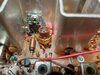
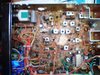
You found a part number, you might want to take a picture - and show us where the part is at. Or just take a picture of the radio with the covers off so we can also IDENTIFY the board type it uses - for different board types were used in the same "wrapper / case" and we have had to sort out all that fun - for years...
Each radio model is a "platform" for specific level of features.
Cobra 19 was a basic radio used Volume, Squelch and Channel - not much else (CB/PA and maybe ANL)
Cobra 21 had a few more features... Volume Squelch and Dynamike (a form of Mic gain) and maybe CB/PA and ANL)
Cobra 25 has more than the other two, lesser brothers, the Radio has what the other have, and NB (Noise Blanker) and RF Gain - so each radio has more complexity and circuits in the radio to perform all those extra duties.
Cobra 29 is about the highest level you can get in AM only radios in AM modes today - at least it is the most common and is considered a workhorse while the 25 is considered it's little cousin - both are used more than nearly any other type - to go to the next level - requires a larger investment in both money and knowledge to use all the features this new level takes you.
One of the many problems in fixing radios- is the sheer number of different boards, but they all do the same thing using nearly identical - same circuit design - but their layouts are different.
Might need to see what you're up against.
Well, I know your new, remember that resistors have power flowing thru them - be careful!
The "voltages" are important to know, it's why some service manuals offer "Voltage charts" They tell you to find a specific transistor (semiconductor) and by checking it's leads under specific conditions- a test - so to speak. The part tested will reveal a voltage to each pin you test - one lead to the pin, the other to a known good GROUND - not case, foil board ground - which is the same ground as the Negative or black battery power wire solders to - the RETURN.
It's not the best but I hope it helps!
So - if the radio is working - the parts - like those resistors - will have power in them. A resistor has two leads, one usually is powered - or it will have a voltage - the other side, if it's grounded - won't have any power - the Negative or Return; the foil ground - took it all away.
The radio also has three sections, One - the Receive including RF Gain, Squelch, Volume NB/ANL (the stuff for your listening pleasure), Two - The Transmit, Dynamike, Microphone - and third (3rd) which usually has power all the time, is Audio (Volume) and PLL (lights and channel display are part of this "always powered" notion). So the radio switches power to route between these sections automatically when you use the radio.
So, in RX mode - your radios' "Green light" - Section one (1) is powered and works with Section 3. Section 2 is powered off - so it doesn't turn on while you listen thru Section 1 to Section 3.
IN TX mode, - The Radios "Red light" - Section 2 works with Section 3 - Section 1 isn't powered completely.
It's when you replace a ton of parts and don't seem to get anywhere, some of those parts are no longer made, you might want to dig thru those you pulled/unsoldered and check them. They may still be good.
You mentioned R50. Well can you read a schematic?
You found a part number, you might want to take a picture - and show us where the part is at. Or just take a picture of the radio with the covers off so we can also IDENTIFY the board type it uses - for different board types were used in the same "wrapper / case" and we have had to sort out all that fun - for years...
Each radio model is a "platform" for specific level of features.
Cobra 19 was a basic radio used Volume, Squelch and Channel - not much else (CB/PA and maybe ANL)
Cobra 21 had a few more features... Volume Squelch and Dynamike (a form of Mic gain) and maybe CB/PA and ANL)
Cobra 25 has more than the other two, lesser brothers, the Radio has what the other have, and NB (Noise Blanker) and RF Gain - so each radio has more complexity and circuits in the radio to perform all those extra duties.
Cobra 29 is about the highest level you can get in AM only radios in AM modes today - at least it is the most common and is considered a workhorse while the 25 is considered it's little cousin - both are used more than nearly any other type - to go to the next level - requires a larger investment in both money and knowledge to use all the features this new level takes you.
One of the many problems in fixing radios- is the sheer number of different boards, but they all do the same thing using nearly identical - same circuit design - but their layouts are different.
Might need to see what you're up against.
Last edited:

Start from the beginning.
1 - Check TR21 Collector (center pin) for about 13v.
2 - Check TR21 Base or Cathode of D15 (Zener) for 9.3v.
3 - Check TR21 Emitter or D14 Cathode for around 8.7-9.0v, depending on the Base/Emitter voltage drop.
These are your main 8v regulator components. Without these, the whole radio does not work.
The PLL is fed off of this +8.7-9.0v through R84 (47), then reduced a little to 8.1v by D13, an 8.1v Zener. This also feeds the +V common of the Channel Selector and the LED display.
The Green LED gets it's voltage directly from the Main +13v Power Switch through R98 (680 Ohms), and is shorted by PTT through D16.
The Red LED gets it's voltage through the power switch side of the CB/PA Switch, when in CB mode. The Red LED is also "shorted" by TR19 (2SC945) when the PTT is unkeyed (RX Mode). So, the TX/RX LED should work (in CB Mode on the CB/PA Switch) even if the rest of the radio isn't working.
The PTT line, which when unkeyed, also provides power to half of the Receiver stages. When keyed (Grounded), this unbiases "or turns on" TR16, a 2SA733 PNP switching transistor, and disables the above mentioned RX voltage feeds. It also provides Ground to TR9 (2SC941) the TX Buffer Transistor when PTT is keyed, or +8v RX to disable this transistor.
The PLL main +8.1v Power input pin is Pin 1. If you do not have this voltage, check D13.
The PLL LD or Lock Detect pin, Pin 4, is Logic High (+8v) when in Phase Lock, or Logic Low (0v) when in Out of Lock condition. This does NOT enable or disable the TX/RX switching as above, but it does disable The TX Mixer IC, IC2 (TA7310P) through R70 (1k) and D12 to Pin 7 of the Mixer IC when in Out of Lock, and provides or removes bias voltage to TR9 TX Buffer through R47 (10k) when in or out of Phase Lock, and disables bias to TR2 (2SC1675), the first transistor of the 2nd IF in RX.
Check for 10.240 MHz signal at R69 which goes to Pin 4 of IC2, the TX Mixer IC mentioned above. Preferably on the IC side of the IC, so as to minimize loading of the Crystal Oscillator. You can adjust the frequency by VC1 to as close as possible to 10.240 MHz.
Assuming the PLL IC (TC9106 or SM5126 or KEIC 25LTD/Cobra25LTD) is functioning correctly, check the VCO frequency at TP3 by FET1 (2SK192) on CH 1 in RX, it should be 16.270 MHz, and 16.725 in CH 1 TX when keyed. While using a voltage meter on TP2 (Pin 7 of the PLL or R59 (10k) or R79 (4.7k)), Carefully clean the wax out of L15, the VCO, and in RX on CH 1, adjust L15 to be around 2v on TP2 (Pin 7), and should be around 4 to maybe 5v on CH40 in TX. Re-melt the wax in the hole to lock the VCO slug in place.
Change the Channel Selector to CH 20, and using an Oscilloscope on TP3 (by FET1 above), adjust L16 for maximum amplitude on the scope.
Once you get to this point, we can go through the rest of the circuit.
Also, this PLL or series of PLLs (TC9106/SM5126/KEIC 25LTD) do not use Binary Code or BCD programming to the PLL Channel Selector, it uses the same 7 Segment LED codes that drive the LED Display, then interprets that in the 1st stage of the internal ROM, if it "sees" an Invalid Code, it turns the Lock Detect off (0v), disables the radio. If it "sees" a Valid Code, it goes to the 2nd stage of the ROM to the Programable Divider. This is to save a few "Bucks" on each radio produced, by using 2 Channel Selector Wafers, one for the "Ones", 2nd for the "Tens", instead of the 3 like used in the Cobra 29 series or 148 series, which have 2 for the LED displays, and 1 for the PLL programming (BCD in the 29 series, Binary in the 148).
.
Mark, just wanted to slip in a message to let you know that I hope you beat this radio.....and get it working better than new. Best of luck....
Andy, about then Voltage......QUOTE]
B
baconater4749
Guest
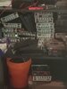
Here is a pic Andy. I have not gotten to the radio yet,possible this evening. I have to tear a pool down,what fun. It is just a old fashion price of junk, this is what I like to work on it is a challenge, if I cannot fix it, I take a shotgun to it,it seems that is what a majority wants me to do,as I like to try at least,I am no brain,but I always give a effort.I will update soon .
Attachments

Sigh...Tools I wish I had still...
Hey, it is a long story, let's get thing thing working...
When you're ready...
Hey, it is a long story, let's get thing thing working...
When you're ready...
OK,I am ready, it is 4:00 P.M. Central,,Indiana time,,I will be here? In and out,10 Min interavals..
I had to replace D2, and it is blown again,,,I put in a 30Volt Pin Diode, IN4751A. Is this a 1S1588?Sigh...Tools I wish I had still...
Hey, it is a long story, let's get thing thing working...
When you're ready...
B
baconater4749
Guest
Hey fix it,resistor R40 the o e in the back with a rubber on it. It was hard to see,so you tend to forget it,I figured what's the difference,a Resistor is a resistor. Well, guess what,if was a Crispy Critter,now I need to back track and figure why it petrified.Is this the way to do it,is backtrack and figure why it smoked,as for the tuning and no voltage,the Diode D2 had the wrong Diode in it,it was apparently not supplying enough voltage to adjust the 3.5Volts. And when it would not transmit after that,I found that Resistor this afternoon,by luck or professionalism,( NOT ). All I can say,I will leave you all alone from now on, if I have a radio that I cannot figure out, I will spare you the trouble of asking anyone for any ideas, advice, or help information. THANK YOU FOR ALL OF YOUR HELP AND INFORMATION THAT WAS GIVIN TO ME. For that,have a great evening, and stay safe, it was nice working with all of the Techs. Goodnite,
Attachments

B
baconater4749
Guest
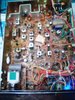
Hey,here are a few pics of the same chassis,I am new at the Cell Phones, this is what I am using,the computer is a pain in the CB radio.I appreciate you doing this, have a great day, I thank you, I will give it a whirl,and now the stupid green RX light is out,maybe I should BURN this one,and go to the next. See pic #4, and you will see what I mean. Wanna be my teacher,video conference, I'm game,are you,or Chicken. Have a safe day,write soon,gonna copy your help,and set it by the radio and read., And work.goodnight.
Attachments

What is going on here all of sodden there are two posts here. Probably the second person ..baconater474.. should start his awn thread so not to confuse things here. It would make things more easy for some to follow and for the people helping less confusing. This is called Hijacking a thread. LOL
dxChat
- No one is chatting at the moment.