• You can now help support WorldwideDX when you shop on Amazon at no additional cost to you! Simply follow this Shop on Amazon link first and a portion of any purchase is sent to WorldwideDX to help with site costs.

Cobra 25 LTD Classic, no voltage change tuning

HA, I love it when you put up schematics and talk dirty like this!
It made me so excited I took the 25GTL schematic in for a deep session tracing every "functional block" being sure that I understood the flow of the entire radio .... at least in a "gnats eye view of New Your City" kind of way. There was a lot of "meat on them bones" in both this and the Uniden 66 thread that you referenced.

I also hope you have a good sense of humor because I do mean this in the most respectful way!!! Thanks!!!!!

Bob


This is for the Uniden made style - PC-417 board.
Since your photo has what looked to be a earlier KEPC board - they "kept" Unidens' style of layout using the Hand-Drawn or "analog lazy-wander" of foil traces. The above schematic - I wanted to point out several things....
........................................
Now, your message sounded a little confused, so let's stop here and I'll let you explain the rest...
 
For a dinky radio, they really did the "Readers Digest" Condensed Version in parts count for the performance it has. Hard to improve on it..

I still have one Cobra 21 GTL and LTD units - both have the PC-417 board, just unpopulated - so as time progresses, reminds me of the time I owned a Chevy Sprint - a little 3-Cylinder engine car, the 21 is similar - just make the Final payment and for $19.95 they'll send you the parts and instructions on how to install the NB section and a little sticker to put over the "21 to make it a "25" :)

So yeah, you Do need a sense of humor around here, but be advised that I tend to take posts dealing with radio more of "Face value" I do take pain and "gifts" a little more seriously - o_O
 
Following @NZ8N - his Lead...
View attachment 45172

This is for the Uniden made style - PC-417 board.
Since your photo has what looked to be a earlier KEPC board - they "kept" Unidens' style of layout using the Hand-Drawn or "analog lazy-wander" of foil traces. The above schematic - I wanted to point out several things.

L16 drives BOTH RX and TX modes. So IC2 being the TX Mixer, may be at fault but then you have other work to do.

You should have signal ALL THE TIME on TP3 - only it shifts 455kHz when you switch between RX and TX.

IC2 can produce work, but the way that the Band Pass Filter in L18 is, may be more of a problem than any 7310 Mixer.

L18 is pretty stringent on what must work for it send any signal to L17.

So let's look at logic.

If you have RX receive, TP 3 shows 16MHz in RX mode, but in TX mode it fails - then a test that the PLL produces to self-check itself - is not being met.

That is where D12 and D18 play a role in helping the PLL do a self-check and make sure that it is producing RF.

D18 goes to the RX side, where the radio uses it's 10.240 clock, used to "down mix" the 10.7 IF - AFTER CF-2 - it should be 455kHz and doesn't need much of a signal to rectify - so it sends it thru D18 back to the PLL when the PLL is in RX mode - there is enough of a signal present so it stays "in lock" and RX works.

But D12 needs the 16MHz with the 455kHz "shift" missing (straight up 10.240 and 16.945 = 27.185 / Channel 19).to work with the 10.240 present at the main Clock back at the PLL - so it "looks" at Pin 7 of the IC TX Mixer, if you are not getting a strong signal - check the slugs and make sure nothings skewed or out of the ordinary at L18 - that is a dual core "stinker" (as I call it) for if it is not tuned right, the rest of the TX mess won't fire up and work for you - the PLL keeps pulling it down because the L18 is a very tight filter and even prevents signal passage when the 455kHz Shift exists.

At the PLL - Pin 4 is where this signal arrives, needs to be about 6 to as much as 7 volts to tell the PLL to work. If it (signal from either Mode RX or TX) is not there - The PLL "stops".

At PLL's Pin 8 - there should be NO voltage present in RX, but 7~8VDC when in TX - Refer back to This posts' Voltage Chart.

So Check the T/R pin on the PLL too - if it's not shifting - the PLL won't lock it in and put on the RED TX light and show RF power.

IC 2 even if it's not "right" you'll see something at D12 .- Because L18 it seeing 10.240 and 16MHz at TP3 - it's using TR16 to "turn on" then the Mixer works - so check TR16 AGAIN - make sure you're sending the Mixer 8 volts so it can turn on and produce the 27MHz for the rest of the strip.

Even if IC2 fails, it's when you don't have TX and yet you have a RED LED - THAT is you need to worry about IC2 and following TX strip down stream having bad parts.
Gonna try and follow your procedure of repairs, I am not very fast,but will give it the old college try.
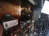
I got help back today putting a final in a antique, I posted a pic, do you or anyone have the alignment for this beast, if not oh well, I may wing it. I don't want to wing it, frequencies galore here, if no manual,it will be as it is, only 3 watts,,look out, get out of the way. It a screamer.
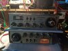
Cobrav138, 23Channel, SSB
 

Attachments

  • IMG_20210610_194616363.jpg
    IMG_20210610_194616363.jpg
    2.3 MB · Views: 12
Hey,quick question for a friend, he works on radio's, or is trying, where are the frequency check points on a Cobra 29 LTD Classic. I have been a bit busy helping out with senior citizens, my Father and my Mother-in law who has Alzheimer's disease. And my Father just needed a few things fixed,84,so he is not to much of a problem, as long as he gets what he wants fixed. But my Wife has her hands full, her Brother is 54, and still lives with him Mother, and cannot help out as much because he is to stoned all day long. So, we have been going and checking on her, take her out for lunch and or ice cream. Honestly, I am not to happy having to do this, but it is kinda nice to see her Mother, but every day of having to see a person go through this terrible disease is so sad ,it is actually sickening.
OK,I will get to the radio soon, and I printed your information to have with me at the bench. All I and or we, please can he have the point for frequencies on the Cobra. Thanks, I owe you about 8 cold ones, talk soon,,Thank AGAIN
 
Last edited:
Hey, I got the radio transmitting to my Icom, buy I cannot seem to transit over the air, I hear myself speaking, but I get no reading on the watt meter,no voice out the antenna plug? Got good modulation,but just can't get to transmit over the air, what am I missing, have my frequencies,just my voice is stick in the radio. let me out.
I found a Diode bad,it was the RX,. Tx Diode,D19 I think, after I replace d the Diode, I set my frequencies, and was able to get the voice out to another radio,but no transmit. I am confused now..
 
Last edited by a moderator:
Frequency Checkpoints...

On a Cobra 25, there are just two - well more if you're curious.,..

upload_2021-6-16_13-6-52.png

TP3 is the main one - that one not only is the PLL/VCO out to grab the channel - it also is how much signal you have from the VCO to work with. So you use TP3 to determine the 1St IF Mixer frequency, and the QUALITY of it - on a scope P-2-P.
  • - the IF is between 16 to 17MHz - and starting at channel 1 - 16.27x - BUT IN TX it's 16.72x
  • That difference is that 455kHz shift - you'll see it all on TP3
  • The "x" is relative, it can bounce between 3 to 2 to as high a 5.
  • In TX, to "center" you adjust your 10.240 X! - with TX on TP4 (your 27MHz) R46 and R47 in TX section
  • 10.240 is adjusted thru VC1 or if none, choose value used at C111 to trim it up higher or lower to get it closer, can't always hit the exact - but unless you have VC1 (a variable cap) there's not much you can do. Except plug in values until you can get its' last digit to 4 5 or 6 - at TP4 that would be 27.184 to 27.186 - you're ok.
upload_2021-6-16_19-35-40.png

Check your connections, look for your soldering and make sure no shorts.
 
Last edited:
  • Like
Reactions: tecnicoloco
Getting no 27 or 16 MHz now,need to order crystals,changed all diodes,all diodes put in according to schematics. I get funny readings, bouncing all over in hz, no MHz. Turn the pots to find MHz, nothing in MHz.
All I can see is the crystals,10.240, I'd getting 5 volts,nothing on 16,695 crystal 0 volts, do I need to search for a bad Resistor,or Cap. Gonna signal trace 16 MHz area. What do you want me to try next,having issues getting receive back,I have 10.240 on TP at R88 the first check point,this is were I am at,stuck here,waiting on 16.695 crystal.
 
Hmmm....

First - you tell me this...
Hey, I got the radio transmitting to my Icom, buy I cannot seem to transit over the air, I hear myself speaking, but I get no reading on the watt meter,no voice out the antenna plug? Got good modulation,but just can't get to transmit over the air, what am I missing, have my frequencies,just my voice is stick in the radio. let me out.
I found a Diode bad,it was the RX,. Tx Diode,D19 I think, after I replace d the Diode, I set my frequencies, and was able to get the voice out to another radio,but no transmit. I am confused now..

So that means you HAD 27MHz and a 1st IF ...

Then I get this...

Getting no 27 or 16 MHz now,need to order crystals,changed all diodes,all diodes put in according to schematics. I get funny readings, bouncing all over in hz, no MHz. Turn the pots to find MHz, nothing in MHz.
All I can see is the crystals,10.240, I'd getting 5 volts,nothing on 16,695 crystal 0 volts, do I need to search for a bad Resistor,or Cap. Gonna signal trace 16 MHz area. What do you want me to try next,having issues getting receive back,I have 10.240 on TP at R88 the first check point,this is were I am at,stuck here,waiting on 16.695 crystal.

Ok, what did you do during this process?

Did you remember to put on or use a Dummy load or put at least an antenna on the Antenna connector?

IF you have all those tools...

To hear yourself talking thru into the receiver of another radio - It meant you were broadcasting, quite possibly the Final was bad, can't tell now.

But you were able to use the Driver to at least "modulate" - you were able to hear yourself on another radio - so that meant you had at least got audio and what RF the Pre-driver was producing - into the Driver to make some form of modulation you heard on the other radio.

For if Audio couldn't get to the Driver you would not hear audio, or the RF couldn't make it to the Driver, you would only have a very weak Carrier, no audio

By your word, you did have carrier, enough to hear you talking thru another radio - at one time...

Now, it don't.

But "you did", so what did you do, to the inside of the radio, to now make it so "it doesn't".

Best to work in stages, think it thru, you know you have to make the TX strip functional so why replace a bunch of parts when we haven't even tested the Final or even checked for bad or poorly soldered connections?

upload_2021-6-22_12-38-46.png

You won't have much luck using just a 16.965 MHz Xtal - the PLL needs 10.240 to make the channels work - it makes that ~16-17MHz signal - and that requires L15 to be able to make D11 Varactor Capacitance effect "Ring" with L15's coil - TR11 amplifies this and sends some of this back to the PLL to keep L15 and D11 ringing - other part goes to TR12 gets amplified, sent to L16 then to TP3 AND TX Mixer IC2 together (and your L18/L16 mess).

IC2 stays off until it's told to turn on thru TR16 - TR19 turn off, turning off your RX light letting TX light go on.

So if you don't have ANY signal on TP3 - the L16 - L15 need to be checked - you go back to TP-2, that R59 - and look for voltages - reset the channel selector to Channel 1 see if you get any voltage on TP 2, then tune to Channel 40 and review the same - does 4 volts or so show up? Tune L15 to get this - L16 will help "balance" RX and TX with L2 and L3 of the RX side helping "equalize" the RX band plan..

IF you can't get it to ring, remember C101 and C102 - those 2.2uF Electrolytic caps? Use Fresh known good and install Positive to Positive or Negative to Negative until you have signal - you have to make that part of the loop work.
 
Last edited:
  • Like
Reactions: tecnicoloco
All I can tell you is I was doing the P to P and it was 3:45 AM, and I went to get the paper,and just shut every thing down. And yes, I had my a Icom IC-R71A communication receiver out and set at 27,185 mhz, and I was able to hear myself, but no movement on the watt meter. My frequency counter quit on me yesterday, I have one of those 10 dollar ones from Amazon, I can set it using my Function/Arbitrary Waveform Generator,I can trust that it is calibrated as it (Rigol) us a trusted name brand.
I have a new Freak Counter ,costed me around $400.00, I said screw it,get one that does everything, but don't fix the radio for you. All that I did, getting receive dialed in, then was going to do TX,after I made sure receive was on the money,and made sure we had our 10.240, checked TP 3, had out 16+ MHz,a few off on the 27MHz,we were at 24MHz,went to get it close with L16 I believe, as then shut it off. The next day,I don't remember what day, the radio said nothing to me when I powered it on,so I freaked out. Did not have my 10.240,and no 16MHz also. I had my 5 volts to the 10.240 crystal, but 0 volts to the 16.695 crystal.
This is where I am at,and yesterday I replaces about 3 diodes, just because they were in the same circuit as the 16 crystal. I think I am done helping the wife, so I am going to block that circuit in, and buzz it, and I should be getting my crystals, just in case. Any ideas, I will check some diodes,see if the freq is back, and trace the circuit. Talk soon Mark,,Did you want to talk to the other Mark, my Clone?
 
Just a quicky. There is your answer about the da da da Dummy Load.b
 

Attachments

  • IMG_20210622_151321586.jpg
    IMG_20210622_151321586.jpg
    1.2 MB · Views: 9
I followed what you did, until here...

All that I did, getting receive dialed in, then was going to do TX,after I made sure receive was on the money,and made sure we had our 10.240, checked TP 3, had out 16+ MHz,a few off on the 27MHz,we were at 24MHz,went to get it close with L16 I believe, as then shut it off. The next day,I don't remember what day, the radio said nothing to me when I powered it on,so I freaked out. Did not have my 10.240,and no 16MHz also. I had my 5 volts to the 10.240 crystal, but 0 volts to the 16.695 crystal.
I need some help - er, understanding...

"A few off on the 27MHz we were at 24MHz" - how did you determine that?​

With L15 you just follow the voltages on TP2 - the radio tries to lock in on that looking thru Pin 9 and the "gating" results on Pins 7,6 and 5 (Pump Charge) through C101 and C102. Both caps are tied, being used as a gated loop with the internal divisor the PLL uses. Channel 1's voltage on TP2 should be low, about 1 volt or so, while channel 40 pushes the Varactor voltage to about 4V.
  • If the PLL is alive, but L15 is not ringing, TP2 shows a "ramp" steep rise slow fall - trying to make the Varactor ring with L15 - checking it thru TR11's output sent back into PLL's Pin 9.
  • Best to tune L16 to maximize RX IF for image at this stage of repair.
  • Then Retune L16 during final tuneup to equalize performance of RX and TX
The Varactor D11, a 1SV63 is about 22~26pF at 1 volt can be as low as 6pF when it tries to lock on 40 - this voltage pulls at the junction layer, making this gap smaller - lessening the capacitance - raising the resonate frequency combined with L15's inductive behavior. Going to channel 40 changes (lessens) D11's varactor capacitance Pushes up the resonate ring frequency Pin 9 sees from the output of TR11

TR12 just buffer amps the TR11 results and shoots it two ways, one to TP3 the other to IC2 - thru L16
  • - so L15 is your CRITICAL component. You have to get it ringing to even push a signal into TR12 and L16.
  • - so if you're not getting anything at TP3 - a new Crystal Filter is just going to sit there - just like it's predecessor
    • - so don't throw too much into the radio for the parts you may need to fix it are more important right now to make it work.
 
Sorry not 24,can't read my own writing. I leaked out the recei e again,peaked out 16,only have .680 for the VCI,there was all the frequencies at all test points again,set the 3.5,I walked 3 feet to grab my phone the post, and now,all of the correct,or almost correct freqs are gone again,spinning through kHz, and a occasionally a 1 MHz will show up,that's all in the MHz I can find running the cores back and forth,just disappeared again I the blink of an eye.
Should I put the IC2 TA7310P in,or figure out why the freqs disappeared. Goons copy your post and go up to the house and have it with me and go through it. Post soon.
 
This intermittent problem may be with L15 - wonder if wax is clogging up the coil and changing the results you get once it warms up,

So I'd check for heating - on the FOIL side - feel for warm spots - shouldn't be any, but if caps are bad or you have wax and debris caught up in the wax - changing resonance - which can happen due to age and dirt - even the tuning cap below the slug can fail - intermittently due to wax creeping in and flooding the cavity - even if there is no cap there

  • schematically it shows there's nothing there - but even then debris can cause tuning issues with old wax.

IT may need to have L15 taken out and cleaned up - check the bottom "tuning" cap area - if its' crushed, there's' the problem, the slug tuning deformed the coil to a point where it can ring in specific points but simple time and vibration will make the slug to coil aspect tuning shift and you lose resonance..
 
  • Like
Reactions: tecnicoloco

dxChat
Help Users
  • No one is chatting at the moment.