• You can now help support WorldwideDX when you shop on Amazon at no additional cost to you! Simply follow this Shop on Amazon link first and a portion of any purchase is sent to WorldwideDX to help with site costs.

Cobra 25 LTD Classic, no voltage change tuning

I borrowed a freq counter,ok TP2 10.240
TP9 Blue resistor by L14 TX=
TP3 16.480 to 17.450 somewhere there.
With the TP9 BLUE RESISTOR, set to ? On RX and TX what should they be,remind me, 32MHz and change on RX?
Give it to me in plain language,I turn L16 to get the freq,correct.I used V1, the red little adjuster for 10.240.
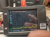
I found 2 solders joined together out of the lines,used solder braid and cleaned them up.I hear noise,have frequencies,a bit jumpy,but I also have this to help.
Oh,I forgot to tell you before I posted the question on the radio.I had 4 Pall's, I thru one in with a socket rail. This radio is ready to go,it is making rumbling and or static,I gave it a quick freq tune,now it's a ready.I am going to p to p the receive,then go for the settings or do transmit,it pops in the speaker and can see it working on oscilloscope.
 

Attachments

  • IMG_20210623_150014560.jpg
    IMG_20210623_150014560.jpg
    2.1 MB · Views: 8
  • IMG_20210623_150644996.jpg
    IMG_20210623_150644996.jpg
    1,008 KB · Views: 8
Last edited by a moderator:
I believe your TP9 "Blue resistor" is an inductor. On some of these boards there is an inductor located in R44 spot. In any case, it will contain 13.8V from the CB/PA switch used to switch on or off the TX side.
  • - when you're in PA mode, it's off (disabled) TX goes dead no power.
  • - when your are in CB mode, R44 / (Or L44 ) is powered thru the CB/PA switch
TP4 is R46/R47 junction Bare wire of R46 - contains 27MHz TX from IC2

You won't "see" a signal at R44/L44 - it's pure DC, has to go thru L14 - which is a "peaking coil" coupling for the Pre-Driver TR9 - so don't get confused with TR9 as TP9 (There is no TP9)

Again; By L14 - R44 should be a 220ohm resistor (Red - Red - Brown), IN EARLY years of production - now they use an Inductor before L14 - used as a Choke.

Also By L14 - R46 (3.3K Orange - Orange - Red) and R47 (10K Brown - Black - Orange ) - used to BIAS TR9
 
Here's why it's very important I know the ACTUAL board number you have.

Because on Later KEPC boards, TP4 was R46 - but in Uniden Days - UNIDEN Made Cobras can use TP1 as a Common Return (shield return) for the Test Leads of the tester - meaning common grounded return - so that means TP4 could be located somewhere different, or as something else.

This is from a PC-417 Board - of Uniden days;
  • - which contains a TP4
  • - also contains a True R44 (220 ohm resistor) Brown Composition style body
  • TP4 is also there - but it's not located where you think...
  • It INCLUDES R48 - a buffer resistor from TP4 At L17's Location - BEFORE it goes to R46/R47

upload_2021-6-23_18-17-3.png
TP3 is still 1st IF Mixer ~16~17MHz signal for Channel RX
However TP1 is Board Ground -
Provides RETURN (Common ) for all other Test Points

Now, you may have a Blue Resistor at R44 - check it, for continuity or resistance - for it is supplying power to TR9 thru L14. These can blow open - it's a smaller wattage rated part for the L14 as a protection - it will blow open before L14 does if something bad were to occur.

They switched to an Inductor for the purpose of fusible-link spot to protect the TX strip.

I supplied a Voltage Chart for you - refer back to it Locate and Test TR9 in circuit - in TX mode - CB/PA Switch set to CB.

You can find it in this post...
https://www.worldwidedx.com/threads...ltage-change-tuning.261922/page-2#post-764614

In the above photo Note R45 lays flat and has bare leads.

It's a 47 Ohm resistor (
Yellow - Violet - Black) - that is the "emitter Resistor" for TR9 - which goes directly to PIN 3 of the MIC socket - so when you TX, Pin 3 is grounded - and lets power flow from R44 - thru L14 - In to TR9 - then thru R45 then to ground at the handset. This let's TR9 produce RF thru L14 - for the Driver.
 
Last edited:
Here's why it's very important I know the ACTUAL board number you have.

Because on Later KEPC boards, TP4 was R46 - but in Uniden Days - UNIDEN Made Cobras can use TP1 as a Common Return (shield return) for the Test Leads of the tester - meaning common grounded return - so that means TP4 could be located somewhere different, or as something else.

This is from a PC-417 Board - of Uniden days;
  • - which contains a TP4
  • - also contains a True R44 (220 ohm resistor) Brown Composition style body
  • TP4 is also there - but it's not located where you think...
  • It INCLUDES R48 - a buffer resistor from TP4 At L17's Location - BEFORE it goes to R46/R47

View attachment 45419
TP3 is still 1st IF Mixer ~16~17MHz signal for Channel RX
However TP1 is Board Ground -
Provides RETURN (Common ) for all other Test Points

Now, you may have a Blue Resistor at R44 - check it, for continuity or resistance - for it is supplying power to TR9 thru L14. These can blow open - it's a smaller wattage rated part for the L14 as a protection - it will blow open before L14 does if something bad were to occur.

They switched to an Inductor for the purpose of fusible-link spot to protect the TX strip.

I supplied a Voltage Chart for you - refer back to it Locate and Test TR9 in circuit - in TX mode - CB/PA Switch set to CB.

You can find it in this post...
https://www.worldwidedx.com/threads...ltage-change-tuning.261922/page-2#post-764614

In the above photo Note R45 lays flat and has bare leads.

It's a 47 Ohm resistor (
Yellow - Violet - Black) - that is the "emitter Resistor" for TR9 - which goes directly to PIN 3 of the MIC socket - so when you TX, Pin 3 is grounded - and lets power flow from R44 - thru L14 - In to TR9 - then thru R45 then to ground at the handset. This let's TR9 produce RF thru L14 - for the Driver.
Hey Andy, a quick note. The buddy of mine with the 29 LTD, I used one of your instructions,I did not get passed one paragraph and I had the radio working like brand new. I followed your instructions you gave me followed them to TR21, had no 13volts I believe on the base during TX,well I put in a 2SA733P,what it had in it,and the radio worked like a champ. I thank you for the information on the 29. I followed the Yellow Brick Road, and it worked. Thanks,this dude that owns the radio thanks you also, he is thrilled, totally, totally,happy. Now, after I clean the bench,I put a TV,50 inch on the wall in the garage next to my work bench,and all the tools and crap are on the bench. It was my wife's idea, (next it's the bed), Ha,. So onto the 25 after clean up. Thanks, have a great afternoon.
 
  • Like
Reactions: Handy Andy
Hey Bud, I recapped the 25, I have TX now, it putting out 25 to 30 watts. YES,I had some time, went recapped the whole think, and 2 caps showed up bad on the tester, did not even read them. I believe it was a 33pf 10v that was bad, and a C45 33pf 50v. OK,I have great swing, but I have NO receive, tried to tune, but no hum, or nothing. I can key up on PA, you can hear it key up but you don't hear nothing.
Gonna look at the Audio section, and make sure the caps are in correct first . I have put them in backwards once, and they do explode, it is like a firecracker, and the there is paper all over the inside of the radio stuck in every Resistor, and what ever it can get wound around, no fun cleaning that up. OK,off I go, I owe a THANK YOU for all of you time, I have learned a whole bunch of good things from you on these Cobra's. Gonna try to get this going. I had to change the mike socket also, one pin I found was broke off, found it sticking of of a mike jack. D you have a schematic or a pic of that little board that is on the side mounted jack, just want to make sure I have them in the correct spots. Thanks...
 
  • Like
Reactions: Handy Andy
Here's why it's very important I know the ACTUAL board number you have.

Because on Later KEPC boards, TP4 was R46 - but in Uniden Days - UNIDEN Made Cobras can use TP1 as a Common Return (shield return) for the Test Leads of the tester - meaning common grounded return - so that means TP4 could be located somewhere different, or as something else.

This is from a PC-417 Board - of Uniden days;
  • - which contains a TP4
  • - also contains a True R44 (220 ohm resistor) Brown Composition style body
  • TP4 is also there - but it's not located where you think...
  • It INCLUDES R48 - a buffer resistor from TP4 At L17's Location - BEFORE it goes to R46/R47

View attachment 45419
TP3 is still 1st IF Mixer ~16~17MHz signal for Channel RX
However TP1 is Board Ground -
Provides RETURN (Common ) for all other Test Points

Now, you may have a Blue Resistor at R44 - check it, for continuity or resistance - for it is supplying power to TR9 thru L14. These can blow open - it's a smaller wattage rated part for the L14 as a protection - it will blow open before L14 does if something bad were to occur.

They switched to an Inductor for the purpose of fusible-link spot to protect the TX strip.

I supplied a Voltage Chart for you - refer back to it Locate and Test TR9 in circuit - in TX mode - CB/PA Switch set to CB.

You can find it in this post...
https://www.worldwidedx.com/threads...ltage-change-tuning.261922/page-2#post-764614

In the above photo Note R45 lays flat and has bare leads.

It's a 47 Ohm resistor (
Yellow - Violet - Black) - that is the "emitter Resistor" for TR9 - which goes directly to PIN 3 of the MIC socket - so when you TX, Pin 3 is grounded - and lets power flow from R44 - thru L14 - In to TR9 - then thru R45 then to ground at the handset. This let's TR9 produce RF thru L14 - for the Driver.
BOARD NUMBER KEPC-063F That is on the back of the board,,,,,,,,,,,,,,,,,,,,,,,,,,,,
 
  • Like
Reactions: Handy Andy
Check your Squelch Control - a bad cap will burn up the SQ pot - so look for the two wires heading to SQ control - short them out, does RX work? The pots opened up - just replace it
 
Check your Squelch Control - a bad cap will burn up the SQ pot - so look for the two wires heading to SQ control - short them out, does RX work? The pots opened up - just replace it
I noticed the transmit cuts in and out, I also have a bad PA switch. If you give it a wiggle,transmit cuts in and out,as I have a switch I am going to throw in. I started to tune,got called away from the wife,it started to hide,gurgle,do what is to do. Boy,someone had fun saying with these pots, what a way out receive it has. Turned up the generator to help pull things together,time to go finish. Looks like another late night for me. 4.00 AM comes very fast when your messing with these radios. OK sir,back to the grime. Have a safe and fine evening.
 
Check your Squelch Control - a bad cap will burn up the SQ pot - so look for the two wires heading to SQ control - short them out, does RX work? The pots opened up - just replace it
Gonna check it out,and let you know,Thanks,good to know,
 
Gonna check it out,and let you know,Thanks,good to know,
This is where I am at,the squelch adjustment pot was shorted, replace it,but I seemed to have lost receive. When I turn the dynamite adjustment,at full turn the radio keys up ij transmit,without pushing the microphone button, and makes a loud buzzing noise? I replaced this also,but no change. I put in a IC2,, mixer, thinking this was a problem with the radio going into transmit when turning the Dynamite adjustment, but no change.
So,no receive,keys up on transmit when turning Dynamite all the way up,this is a issue I need to track down. I need to look at the side mount microphone wiring board,seemed it was messed with before I received the radio. With the broken #3 mike pin, it looked like it had been soldered on before. Going to pull schematics and check wiring on board,and see if it is wired correctly. I put it back the way I found the wires on the board,may be put back before me wrong,possibly wrong. Otherwise,getting somewhere.. I am about to throw this radio out the garage window,just a total nitemare, I appreciate you sticking with me and this worse nitemare,gonna give it 2 more tries before I blow my mind. How about doing a 29 LTD,hah.hah. Seems that I stuck on these Cobras.
 
Going to pull schematics and check wiring on board,and see if it is wired correctly. I put it back the way I found the wires on the board,may be put back before me wrong,possibly wrong. Otherwise,getting somewhere..

Yes, when Dynamike starts making the radio key up, then yes, you have a wiring issue or two.
 
Yes, when Dynamike starts making the radio key up, then yes, you have a wiring issue or two.
Black zip ties all through the harness,I may have a 25 wiring schematic on my other laptop. I will look tomorrow,just what ,I need, thanks will look into it.
 
I have some older works from the CB Tricks days that may be able to help you decipher the wiring problems people seem to have with these radios.

Don't know why or how, you got into this predicament,
But, in your situation this info can possibly help...

upload_2021-7-3_11-30-28.png

Pay close attention to the Mic plug to board wiring.

Schematically- they do apply several "RF bypass" caps...

upload_2021-7-3_11-42-45.png

So be aware of the Case to Board grounding issues and
know too, that they route wires to a spot on the Main PCB, that
is ISOLATED from both types of grounds
- Foil and Case (Chassis)
and they branch off from there...
 

Attachments

  • PC66MicJackSideview1.jpg
    PC66MicJackSideview1.jpg
    234.1 KB · Views: 7
Andy,get to it later today,it is midnight now,just taking a quick look at the radio. I did not notice that somebody has been messing around in this radio. I am wondering if this is a lost cause,as I have a buddies 29 LTD sitting here I need to look at,soon. It keys up,you can see it on the oscilloscope,it keys,spreads the double voltage line,but you can barley see it on another radios meter,. Nothing transmits,but you can hear and barley see it. Thats my next job,hopefully he did not play with this. Talk soon,wife yelling for me Later.
 
Andy,get to it later today,it is midnight now,just taking a quick look at the radio. I did not notice that somebody has been messing around in this radio. I am wondering if this is a lost cause,as I have a buddies 29 LTD sitting here I need to look at,soon. It keys up,you can see it on the oscilloscope,it keys,spreads the double voltage line,but you can barley see it on another radios meter,. Nothing transmits,but you can hear and barley see it. Thats my next job,hopefully he did not play with this. Talk soon,wife yelling for me Later.
Here is a picture of the Dummy Load I am using?
 

Attachments

  • IMG_20210714_001918661.jpg
    IMG_20210714_001918661.jpg
    1.2 MB · Views: 11

dxChat
Help Users
  • No one is chatting at the moment.