I don't have the pa wiring in here anymore, rx and tx sound exactly the same. The audio IC is the one bolted to the chassis, about 1" long? I have another in the donoryou just said your TX audio and PA is the same. do you have a good audio IC to replace the one in this radio with. just saw it was caused by a short also. you may have blown the audio IC. I had a radio doing this last year and it was the ic bad. found out the radio had been shorted and was getting popping noises in PA and TX mode also.

You are using an out of date browser. It may not display this or other websites correctly.
You should upgrade or use an alternative browser.
You should upgrade or use an alternative browser.
-
You can now help support WorldwideDX when you shop on Amazon at no additional cost to you! Simply follow this Shop on Amazon link first and a portion of any purchase is sent to WorldwideDX to help with site costs.
-
A Winner has been chosen for the 2026 July 4th Retevis RA89R Giveaway! Click Here to see who won!
Cobra 29 nw ltd classic, no receive.
- Thread starter Ay589
- Start date
Check the audio ic with your multimeter and reference the service manual for the correct voltages.
Also, there are 3 different audio chips for the 29. Depending on when you r radios were made. The older ones had a 10pin chip, ta7222. Later models used a 10pin chip, yd1022. It will not interchange with the other.
3rd is in the newer radios which is a 5pin chip.
Just make sure they are the same before you swap them.
I will, also my radio is a 29 nw ltd classic. I can't find a specific manual for that, all I come up with is the 29 st nw whatever. I do not have night watch, as far as the complete radio inside and out, it looks 100 percent like he regular 29 besides the little ac power converter supply for the night watch. A link to a proper pdf manual would be greatly appreciated.Check the audio ic with your multimeter and reference the service manual for the correct voltages.
Also, there are 3 different audio chips for the 29. Depending on when you r radios were made. The older ones had a 10pin chip, ta7222. Later models used a 10pin chip, yd1022. It will not interchange with the other.
3rd is in the newer radios which is a 5pin chip.
Just make sure they are the same before you swap them.
Okay, I know you didn't intend to blow up the radio, but we still refer to this sort of fault as a "sabotage" fault. Doesn't mean you intended to damage the radio. Just means that the fault is some random failure of something that NEVER goes bad on its own. A lot of the skill used to fix radios has to do with the stuff that goes bad most often. A knowledge of the ten most-common things that go bad will allow you to fix nine out of ten radios without pulling out a lot of meters, signal generators, 'scopes, counters and all that stuff.
A random fault is different. Requires tracing it down by following the circuits that DO work until you arrive at one that isn't working.
Replacing TR13 didn't fix the problem.
Means that it wasn't causing the problem. TR13 is the squelch transistor that shuts down the receiver audio. Since removing it only gets you part of the receiver audio, that means that the squelch circuit is only part of the problem. But we do know that the squelch circuit is being activated when it should not be. Just don't know why yet.
Sure would be nice to know just where that resistor touched on the pc board.
Even if you have all the fancy tools, this sort of failure is the most troublesome to troubleshoot. Things that routinely go bad are a lot easier than a random fault that never happens on its own.
If you haven't got a basic meter to read voltages, it's going to be like changing spark plugs with a two foot-long channel-lock plier. Just won't reach down in there. Gotta have a socket, extension and a handle to twist it. No other way.
Whatever it is that the loose resistor caused to fail should cause one or more voltages in the radio to be wrong. Besides, if you suspect that a part is bad, having a way to test it is better than just changing parts one after the other to see what happens. This creates the risk of causing a new problem if swapping a part goes wrong in some way, like a solder bridge or getting the part turned the wrong way putting it back in.
But that's the only way to zero in on it. Unless you can point to the exact spot where the resistor touched. That would help a lot.
Oh, found the schemo for the NW LTD ST model: http://downloads.cobra.com/CB/Models/29-SERIES/TDA2003_Audio_Amp/29NWtda2003schem.pdf
73
Last edited:

Absolutely. I have a decent multimeter, Klein mm200. And this is why I want somebody with knowledge to chime in possibly. So that I don't need to go around swapping parts back and forth and possibly cause a whole new problem like I have stated previously. I build replica antique guitar amps like a 59' fender baseman etc, so I've got a decent start when it comes to electronics, soldering and proper orientation, but if you don't understand the basic circuit you're screwed! That's what I'm scared of, even the best tech can leave a solder blob on somewhere or put a cap in backward by accident, (late night, Distractions) and poof!!!Okay, I know you didn't intend to blow up the radio, but we still refer to this sort of fault as a "sabotage" fault. Doesn't mean you intended to damage the radio. Just means that the fault is some random failure of something that NEVER goes bad on its own. A lot of the skill used to fix radios has to do with the stuff that goes bad most often. A knowledge of the ten most-common things that go bad will allow you to fix nine out of ten radios without pulling out a lot of meters, signal generators, 'scopes, counters and all that stuff.
A random fault is different. Requires tracing it down by following the circuits that DO work until you arrive at one that isn't working.
Replacing TR13 didn't fix the problem.
Means that it wasn't causing the problem. TR13 is the squelch transistor that shuts down the receiver audio. Since removing it only gets you part of the receiver audio, that means that the squelch circuit is only part of the problem. But we do know that the squelch circuit is being activated when it should not be. Just don't know why yet.
Sure would be nice to know just where that resistor touched on the pc board.
Even if you have all the fancy tools, this sort of failure is the most troublesome to troubleshoot. Things that routinely go bad are a lot easier than a random fault that never happens on its own.
If you haven't got a basic meter to read voltages, it's going to be like changing spark plugs with a two foot-long channel-lock plier. Just won't reach down in there. Gotta have a socket, extension and a handle to twist it. No other way.
Whatever it is that the loose resistor caused to fail should cause one or more voltages in the radio to be wrong. Besides, if you suspect that a part is bad, having a way to test it is better than just changing parts one after the other to see what happens. This creates the risk of causing a new problem if swapping a part goes wrong in some way, like a solder bridge or getting the part turned the wrong way putting it back in.
But that's the only way to zero in on it. Unless you can point to the exact spot where the resistor touched. That would help a lot.
Oh, found the schemo for the NW LTD ST model: http://downloads.cobra.com/CB/Models/29-SERIES/TDA2003_Audio_Amp/29NWtda2003schem.pdf
73
I like how you're on the same page as me with the fact that you can have all the fancy tools out there, they aren't 100 percent necessary, they just make it a lot easier! That to me shows you have experience! Anyone who says you need every tool just to figure it out isn't experienced in my eyes, the proper basic tools are necessary! But not every scope meter noise maker etc fixes it! They buy huge computers to diagnose cars, but still half the problems the computer states are bad are wrong and it comes down to a gas cap
But basically I am stuck to the path of testing what I can understand, and swapping out the rest. But I don't want to do that anymore.
So removing tr13 didn't just give me half receive back, it also allows me to transmit. otherwise my transmit voice was silent,
this is the info that helps a lot also, understanding what tr13 does and learning what the rest of this does. That's the problem, I kindof have the area that the pliers touched down to a 3" square area between the audio chip section to the power feed as that's where the pliers were when I flipped that radio back up like a hot pancake freakin out!
Thank you for the schematic but I am concerned that doesn't cover my model. Since I do not have a 29nw st, it is just a 29nw. No sound tracker, which had some extras in the circuit that throw me off.
I really really appreciate every piece of advice I get! And each piece I receive gets my that much closer to this! Someone said to me not to waste the time on this, (he's been through 4 wives and only 30)! haha Id rather spend my time learning everything I can and fixing dead things I never could before!
Once again thank you all, keep the info coming!
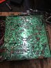
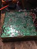
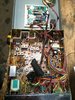
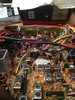
Get a magnifying glass and start looking at the trace side of the board for a broken trace or a burnt spot where the object touched. You may already have this and done it, but if not, wouldn't hurt. It may be such a small spot that your eyes alone won't see it. And keep at it man. You'll find it. Might take some time, but you most likely can find it.
Also like I said in another post, if you can or care to post some photos of the board, it might help with diagnosing the issue. More eyes are always better!!! Just some food for thought man. And again, hope you get it fixed.
Also like I said in another post, if you can or care to post some photos of the board, it might help with diagnosing the issue. More eyes are always better!!! Just some food for thought man. And again, hope you get it fixed.
Absolutely, when I get home from plowing I'll try to get some real good clear pics of the board both sides. Yeah I've searched for a bad trace but you all know, after a Few minutes, everything kindof blurs lol. Kindof like looking for your keys. Once you stop looking you'll find themGet a magnifying glass and start looking at the trace side of the board for a broken trace or a burnt spot where the object touched. You may already have this and done it, but if not, wouldn't hurt. It may be such a small spot that your eyes alone won't see it. And keep at it man. You'll find it. Might take some time, but you most likely can find it.
Also like I said in another post, if you can or care to post some photos of the board, it might help with diagnosing the issue. More eyes are always better!!! Just some food for thought man. And again, hope you get it fixed.
That schematic given by Nomad is still valid and accurate, as this design hasn't changed much in decades.
The NW/ST functions exist on other boards in the radio, and does not change the schematic. Just adds to it.
The NW/ST functions exist on other boards in the radio, and does not change the schematic. Just adds to it.
Last edited:
Thank you!! I just want solid answers on this stuff like you guys are giving me. Google is an endless search for headaches!That schematic given by Nomad is still valid and accurate, as this design hasn't changed much in decades.
The NW/ST functions exist on other boards in the radio, and does not change the schematic. Just adds to it.
IIRC - 'sonoma' (forum member) probably has the exact schematic for your radio.
He may well read this post and have a copy for you to download if he sees this post - I recon.
He may well read this post and have a copy for you to download if he sees this post - I recon.
He was in here in the last page somewhereIIRC - 'sonoma' (forum member) probably has the exact schematic for your radio.
He may well read this post and have a copy for you to download if he sees this post - I recon.
here is the schematic I use for a cobra 29. all are basically the same just a few add ons or the audio chip is different. it shows to be the 29NW LTD
http://downloads.cobra.com/CB/Models/29-SERIES/29NWschem.pdf
http://downloads.cobra.com/CB/Models/29-SERIES/29NWschem.pdf
dxChat
- No one is chatting at the moment.