When I have a radio "fresh out of the box" and no receive, the "hiss" is the IF - a good quantity of it is a good sign that BOTH IF's the PLL one (16~17MHz) and the 10.240MHz (Xtal) IF are working.
But why dead?
Usually due to a bad solder joint - you may be seeing someones' effort at trying to get the radio to work again - but in rare instances - the OEM part is bad, not prime like it should have been and they didn't catch it or worse - they just pushed it out the door.
Some things to help you sort this out is to look for and locate VR1 - you said it had some caps around it - but are you sure it's VR1?
VR1 is the 455kHz IF trim - which does produce that hiss in major quantities if nothing else works.
Don't see any "Bad soldering" here but loud hiss usually means something high gain, but not in the band.
So, you have to go further back towards the Final Driver area and that section that pulls the RF Signal off the main output strip - that area is tricky sometimes.
Even the coils that tune for 27MHz band - some fixes I've had done for DOAs' have had coils gone "open" but nothing serious, if the coil wind from the trace to foil does not show a short but the schematic of it does - takes a good unsoldering tool or braid to remove that cans tabs then it loosens and pops up the cover/case and the coil can be inspected to see if the strands are not making contact like they should.
On to other things to check.
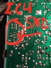
The thing comes with that wonderful "offset" - so double check the T/R function - make sure that PLL pin changes state
View attachment 59322
Thats Pin 9...
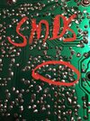
Also related to RF gain, there is a section - two actually, that affect receive and if not wired correctly - will damage TR6 - the RF Gain control - Gain control.
Just locate this little "square" - that square pad helps TR6.
View attachment 59323
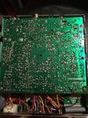
It's best to troubleshoot - to check remove the two RF Gain wires - remembering where they go - and remove TR6 - see if RX comes back in spades - if it does - then you'll have to figure out what took out TR6 - just replace it, but carefully check those wires - it "pulls" RX signal out of the RX input by throttling the PIN diodes.
View attachment 59324
So to have TX work, and the noise to be attenuated, leads me to think the two things - one the T/R pin is not working or the RF gain section is goofed up.