• You can now help support WorldwideDX when you shop on Amazon at no additional cost to you! Simply follow this Shop on Amazon link first and a portion of any purchase is sent to WorldwideDX to help with site costs.
  • The Winners of the three Retevis radios 16 Anniversary giveaway are announced!! Click Here to find out if you won!

Considering a kenwood final on a washington, again.

brandon7861

Loose Wire
I Support WorldwideDX.com!
Nov 28, 2018
2,679
2,976
293
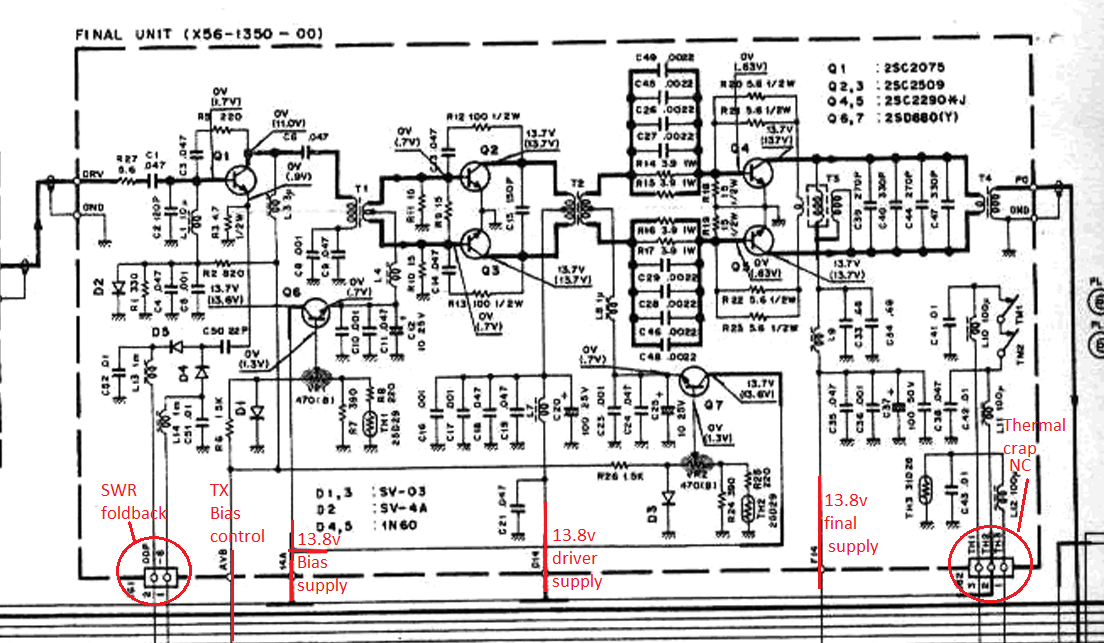
My daily driver is a uniden washington. I have an extra TS-130s final unit and I have been wanting to attach it to the washington for years now but abandoned it due to a lack of knowledge. I think I have the connections figured out now.
1787264607065.png

It would seem the first pair or wires on the bottom is for SWR foldback as it goes to a transistor very near to the directional coupler on the filter unit. I havent analyzed the circuit there, but I would assume bypassing the emitter would increase gain, so I am thinking swapping diodes D4 and D5 with caps and leave these two leads disconnected (or use it as a variable power mod). The thermal protection stuff that drives relays can go too because I don't normally sit on the mic very long. That should leave just the bias control thats TX only and the other three that I figure can connect right to 13v. Of course, the relays and a filter will have to be macgyvered onto a custom board and tucked inside the radio somehow (and shielded, maybe an external box, idk), a PS upgrade and maybe even some hot switching prevention.

I'm not an amp builder so I must ask if this would be ok to run on AM too or if I would need change bias for AM (the TS-130s had no AM). Anyone know if this will play nice with AM?
 

Hey Brandon,

I seen this interesting post repurposing a 757 GX Final (PA) unit to use with a QRP rig with 3-4watts that inputs into a 36db attenuator to reduce the drive to milli watts that the pa board needs.


In the photos he has more descriptions of how he achieved it. Thought you might like to read it for some ideas. Ironically when you posted I had been thinking of doing the same thing repurposing a spare ts430s PA stage I just got hold of.
 
Last edited:
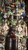
Found the amp in the shed. Looks like someone was already in it. The transistors are new looking and a factory screw replaced. The final thermistor is cracked too so I guess I need to take the board out and look under it.
 

Attachments

  • 20261011_150330.jpg
    20261011_150330.jpg
    1.5 MB · Views: 20
Found the amp in the shed. Looks like someone was already in it. The transistors are new looking and a factory screw replaced. The final thermistor is cracked too so I guess I need to take the board out and look under it.
The TS-130S PA uses 2SC2290. Someone was in it for sure..... My TS-130S, had the worst PA on 10m of all of my Kenwood's.
 
I noticed that too. The cracked thermistor works as it should so i coated it in a thin layer of resin and put it back in. One thing that I don't understand is that all of the 2SC2509 (drivers) datasheets show the middle pin as the collector and this PA grounds that pin and calls it the emitter in the schematic. The datasheet also calls the tab the collector, and it is connected to the middle pin that kenwood is using as emitter/ground.

I have never tried one on 10m, but the good 130s I have down in the shed received nothing but great reports on 11m. I miss making the contacts I did on that radio. I think it was doing about 120w. The band switch wore out and I never got around to swapping it out.

I did a quick in-circuit test on the MRF454s to make sure they are working and they both worked and seemed well matched. I hope it works. I will be searching the shed for the old parts kenwood filter board. I think it will have the inductors and relay I need.
 
Last edited:
I noticed that too. The cracked thermistor works as it should so i coated it in a thin layer of resin and put it back in. One thing that I don't understand is that all of the 2SC2509 (drivers) datasheets show the middle pin as the collector and this PA grounds that pin and calls it the emitter in the schematic. The datasheet also calls the tab the collector, and it is connected to the middle pin that kenwood is using as emitter/ground.

I have never tried one on 10m, but the good 130s I have down in the shed received nothing but great reports on 11m. I miss making the contacts I did on that radio. I think it was doing about 120w. The band switch wore out and I never got around to swapping it out.

I did a quick in-circuit test on the MRF454s to make sure they are working and they both worked and seemed well matched. I hope it works. I will be searching the shed for the old parts kenwood filter board. I think it will have the inductors and relay I need.
Mine did have a nice RX and stable VFO, but the headers and bad soldering intermittent issues, required too many repairs. I slipped on the last repair and it has not worked since. I gave up on it and trashed it.
 
  • Sad
Reactions: brandon7861
I noticed that too. The cracked thermistor works as it should so i coated it in a thin layer of resin and put it back in. One thing that I don't understand is that all of the 2SC2509 (drivers) datasheets show the middle pin as the collector and this PA grounds that pin and calls it the emitter in the schematic. The datasheet also calls the tab the collector, and it is connected to the middle pin that kenwood is using as emitter/ground.

I have never tried one on 10m, but the good 130s I have down in the shed received nothing but great reports on 11m. I miss making the contacts I did on that radio. I think it was doing about 120w. The band switch wore out and I never got around to swapping it out.

I did a quick in-circuit test on the MRF454s to make sure they are working and they both worked and seemed well matched. I hope it works. I will be searching the shed for the old parts kenwood filter board. I think it will have the inductors and relay I need.
My memory, which isn't great these days, tells me the pinout of the driver is BEC, thus grounding the center pin and tab.
 
  • Like
Reactions: brandon7861
I've got a mystery with these 454s. I noticed 23mA of current with no bias. The base is about 8 ohm to ground. I get about 23mA draw with no bias. I lifted one collector and it cut the draw in half. With an ohm meter on the supply rail, I get about 345ohm and it raises a few ohm when hot air is blown on the finals. Going from 12v to 24v only added 10mA. If I power the bias circuit (which I haven't changed) it pulls about 248mA (which seems like it would be right, IDK).

Earlier I had used a 220ohm resistor to go from collector to base to turn on the transistor. At 220ohm I had about 250mA and at 120ohm, it went up to 1.25A. With the 8 ohms or so at the base, thats around .7v so a sharp increase in current is expected. Both transistors raised the current the same so I assumed they must be well matched. With the supply set to trip at 2A, I used a 10ohm resistor to turn it on hard enough to trip the breaker, and it did. Seems like it is working.

When I lifted the collector of one of the transistors, I had 581ohm collector to emitter and 574 collector to base. Polarity did not matter.

Do these 454's have that much leakage? They seem to be behaving like transistors at least.
 
I've got a mystery with these 454s. I noticed 23mA of current with no bias. The base is about 8 ohm to ground. I get about 23mA draw with no bias. I lifted one collector and it cut the draw in half. With an ohm meter on the supply rail, I get about 345ohm and it raises a few ohm when hot air is blown on the finals. Going from 12v to 24v only added 10mA. If I power the bias circuit (which I haven't changed) it pulls about 248mA (which seems like it would be right, IDK).

Earlier I had used a 220ohm resistor to go from collector to base to turn on the transistor. At 220ohm I had about 250mA and at 120ohm, it went up to 1.25A. With the 8 ohms or so at the base, thats around .7v so a sharp increase in current is expected. Both transistors raised the current the same so I assumed they must be well matched. With the supply set to trip at 2A, I used a 10ohm resistor to turn it on hard enough to trip the breaker, and it did. Seems like it is working.

When I lifted the collector of one of the transistors, I had 581ohm collector to emitter and 574 collector to base. Polarity did not matter.

Do these 454's have that much leakage? They seem to be behaving like transistors at least.
What voltage drop do you see E-C?
 
With no bias and 13.8v at the supply, I see the full supply voltage across C-E of both transistors, 202mV on one base to emitter and 207mV base to emitter on the other.

With the final bias supply input pin connected to the 13v rail, the base-emitter of both drop to 153mV and 157mV respectively and the current draw goes from 25mA to 255mA and the collector emitter voltage goes to 13.5v on both. They seem to be behaving like good transistors aside from this mystery leakage when not biased.
 

dxChat
Help Users
  • No one is chatting at the moment.