• You can now help support WorldwideDX when you shop on Amazon at no additional cost to you! Simply follow this Shop on Amazon link first and a portion of any purchase is sent to WorldwideDX to help with site costs.

D&A Phantom 500 resurrection & Re-Tube Need Help hit a Big BumP

giboni

Break Break..Does anyone have any Grey Pupant ?
Sep 24, 2014
119
39
38
66
Nebraska
Hi,

It was laying around for years without tubes except the little tube for the key Up circuit.

Ah over a decade ago re-tubed to 24LQ6 3 Phantoms with 12volt relays & PNP TO-220 high side transistor switch. regulated DC 24v filaments.

Perhaps pre-Alzheimers. forgot a lot of tube theory.

This beast uses 2x110v DC relays. Measured from the low side of the relays a staggering 187v DC !!!!

Grounded to Chassis. The schematic on CB Tricks is for the transistor key up circuit and 12v relays.

Probably can sketch this version's original circuit if I had to.

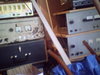
Changes I made. Full wave Bridge Doubler connected to a DC to DC Boost board giving me a steady 31v

DC filament voltage for the NOS 31LQ6.

Thermisitor and delay relay board which switches out the thermy then current flows through the relay. 15Amp
push button circuit breaker.

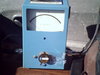
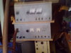
Cool large green led meter next to the filament switch. The red on light is now between the lower load & tune.

The + - of the bridge is floating above ground I think. 2x 10,000uf Elna for the doubler. 1x 6800uf elna for the

DC buck board output. The board itself has a lot of parts caps & 2x regulators heat sinks. Rated at 6Amps to 40v Dc Adjustable output. "10x 31LQ6 requires 4.5 amps at 31v

For the red on off light to work & the relays. 1 side of the AC input to bridge is still connected to chassis.

Also for the key up Tube Filament. One center tap was never used & still not. The others still connected as originally found.

I get the 12v for the soft start relay board from 1 diode & 100uf 16v from one AC side of the Bridge rectifier.

I changed the Very Old Leaky HVcaps to 120uf Nichicons.Skinny & short. Needed the space for the buck boost board & related Capacitors.

Tested Amp with 6LQ6. Went to 3 amp Diodes tested Amp again. Changed out all old capacitors.

Checked again. Did the conversion to 31LQ6

Here is the problem.

1050v DC is applied to the 6 31LQ6 finals Plate on Key-up. 550v is applied to the four Drivers. Switches on High. 250Watt switch off Lo power off.

No output or Amplification ? The cb radio 4 watts simply get lost. I can see a hair of movement on the Co Axial Dynamic meter. SWR between radio and Amp sames as when driving the original 6LQ6s. Acceptable and the same when the Amp worked with original tubes,

It is a - bias problem obviously. Grid number one ? Or is it a Cathode bias problem ? The BJT Phantom Schematic shows a few similar parts placements. Grid tune stands out. CB Trick Schematic is three Stage.

The one I have may have been a three stage. But I think it was turned into a Two stage not sure. Pink

wire DRIVES me crazy ! No color code. At least the mains wires have colors ?

. 3 wire prong conversion using a "gimick" at the ground of the three wire. This gimick connected to the D&A meters. One center tap connected here with resistors & Disc Caps.

My model did not have chokes like the CB Tricks schematic from pin 1 control grid to ground on some tubes.

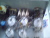
All 10 tubes in my model are grounded grid. I took all 6 filament wires. Put them in proper phase.

Center Taps of HV supply to chassis thru large disc Capacitors are original. One filament center tap drives the RED on Off lamp.

My feeling is I have to make a Bias Supply for control grid one. For the life of me I cannot understand how it is biased with the original tubes.

Any help Appreciated.

Would like to get this Sweep Beasty working ! It actually worked with a batch of worn out 6LQ6s.

Till I golden Screw-drivered it !!!!!!!!!!!!!!!!!!

I also have a Working Warrior that I can re-tube. If I can finish the Phantom?The Warrior ought to be a Breez !

Only Six tubes more ! Ive had this batch of 31LQ6's for years.I finally got around to it !

Best John Any help appreciated.
 
  • Like
Reactions: Shadetree Mechanic

Woke up this morning with a Eureka geezer moment. Try putting the little tube from the D&A warrior into the 31LQ6 Phantom ?

Will post back.
 
Okay I am off today. No handy man work. Have to do laundry ? Ah do it tonight. Back to the Phantom.
Clearly major diferences between the tube key up version with 110v DC relays and the PNP key up version.

Well. Those Pink wires. What a Hassle. Will fallow them from the High low power switch & 250W switch.

Change key up tube....Probably no change.
Perhaps In my rush did not notice that one of the 6vac filaments was connected to something else besides tube heaters.?

I have 39UH J.Miller 39UH RF chokes coming in the Mail.

I will lift all Control grid #1 pins up. Re-check no Cathode bias Circuit. Build a negative grid supply circuit quick with a pot.

That ought to do it. This Beast fully refurbished with new tubes will be back on the Air.

CB Tricks great web site. I looked at nearly all the tube Schematics. Shoosh even looked at a tube audiophiles dream amplifier with 8 6LQ6"s Mchintosh 2500.

Thats where I got the idea to use a pot. While I am at it. Why not an individual grid bias pot for each tube !

Nah This is just a linnear amp anyways
 
Obviously little interest in re-tubing Phantom's.

The best thing for me when hours are piling up and the gadget still does not work. Is to put it away for 10 days.

I realized a huge mistake a few days ago. The bridge rectifier I was using is too small.

Ohm's law. Watts not Amps. I used a 10Amp bridge.. 6LQ6 2.3 Amps 6.3v ac filament current versus 31LQ6 .45 amp at 31v. DC Safe current rating for the Bridge v doubler circuit is 25-35 amps not 10. Snail mail China Post. Another few days. .83 cents each. 50 amp metal bridge 1000piv. rectifiers.

I researched. Forced my Golden Screwdriver brain to do a bit of Math. & found a useful online program.

10 meters 28Mhz the inductance at 1000v of the Tank Coil is .700mh. .675mh at 11 meters..........................ha ha !

For a change. Smaller is better ! 10 turns of 1/8 HVAC soft copper tubing on a 7/8 form.(plain electric cheap conduit that I polished). Coil is 1" inch diameter.

$6.00 at HB with %20 off coupon
stainless digital dial caliper ! .668 Mh on a digital LCR meter. $13.36 shipped.
Tank coils are interesting. Making them tricky.

The solid state Keyup Phantom is different. Should have fallowed it . Ah I learned a lot in a short time. Lot of hours spent ! Learned a lot in a long time ?

The - grid bias supply remains off a center tap of the filament winding. What I will add is a rectifier diode with cathode end attached to the chassis from the filament (6.3v) . Jut like the later
Phantom. The later Phantom used a different Mains transformer. HV center tap. But no filament winding center tap ! The older Phantom Mains have a low voltage center tap on the 6.3 filament winding. Obviously the later Phantom is making the chassis positive. The four driver tubes have a positive bias applied to control grid #1.

This beast will rise up from the dead .....very soon !

Oh don't post about wiring them up in series parallel-the tubes. That shortens tube life considerably.
 
Last edited:
Not that long Wavrider. Look at the dates. But still a long time for no more stuff. Since July 2016. So about 6 months ago he last posted. Please don't take this as me being the date police LOL! Hope all is well. Been hearing some action on 40 meters the last few days. Hopefully soon I'll be able to join in!!! Fingers are crossed to be able to get to Ham Fest. If not I will be taking the test here in Daytona!!! Either way it's time!! Anyhow. Sorry to hijack thread.
To the poster, welcome to the forum and hope you get some answers!!
 
Thanks for the warm welcome guys but I'm the "Suicide Ride" from 10 yrs. ago... I couldnt log on w/ my old password so I look like a "nubee"...

Just thought I'd see if giboni had any luck w/ his project since his last post... (pretty interesting what he's doing with the "old girl").

Btw, if anyone can help me fix my "new member" status, I'd be much appreciative.

SR
 
Not that long Wavrider. Look at the dates. But still a long time for no more stuff. Since July 2016. So about 6 months ago he last posted. Please don't take this as me being the date police LOL! Hope all is well. Been hearing some action on 40 meters the last few days. Hopefully soon I'll be able to join in!!! Fingers are crossed to be able to get to Ham Fest. If not I will be taking the test here in Daytona!!! Either way it's time!! Anyhow. Sorry to hijack thread.
To the poster, welcome to the forum and hope you get some answers!!

I looked at the join date not the post date:rolleyes::rolleyes::rolleyes:
 
  • Like
Reactions: 222DBFL
Hey 222DBFL,
I will not be at hamcation on 10Feb.
Plant manager went under the knife 3FEB17 for back surgery, I am stuck with the show the next couple weeks so Orlando is not in my future,

Good luck on the exam
 
  • Like
Reactions: 222DBFL
Pretty much same here. My boss went under the knife not long ago either for neck surgery. A couple rods and screws later he is not able to work at all anymore. So I pick up the total workload now!! Been a rough few weeks as well for me!! I am still hopeful I'll make it there. And if not, I'll be taking the test here in Daytona! Anyhow. Stay well my friend and have a good one!!
 
  • Like
Reactions: wavrider
Thanks for the warm welcome guys but I'm the "Suicide Ride" from 10 yrs. ago... I couldnt log on w/ my old password so I look like a "nubee"...

Just thought I'd see if giboni had any luck w/ his project since his last post... (pretty interesting what he's doing with the "old girl").

Btw, if anyone can help me fix my "new member" status, I'd be much appreciative.

It has been awhile since I posted this. Illness. Car breakdowns. Working

hard to get back on my financial feet. Making money with my time. Instead of tinkering.

I am on my feet. With time to get back to my hobbies. Working part time till

I have fully recuperated.

This Beast is completed. It works well. Packed up & shipped back to its owner.


I scrapped the voltage doubler idea. I did not like the voltage drop on the

heaters at key up. I tried huge amounts of capacitance in the full wave brige

doubler.

So. I went to an adjustable DC 24 volt switching supply ! Strapped on the

back of the Phantom. Excellent voltage regulation. No drop on key up.

Better than the original 6.3 AC supply ! Step down transformers are dependant

on line voltage. The big Triodes 400, 500Z yada yada have to be AC. Plus

a lot of issues because of constantly changing line voltage.

Rock steady. 24.1 - 24.

Next problem. The Bias. 4x lq6 GG AB1 driving 6x LQ6 in GG AB2.

AB1 Control grid G1 is RF grounded. AB2 G1 is connected to a - grid power supply.


Basically I had to read a lot of Audio tube Enthusiast material to learn.

Sparse in the Ham literature.

The D&A amps use a lot of Gimmicks. A big issue is. No color coding of wires

under neath. My supply of colored markers were a bit helpful.

The Bias circuit used in the D@A is absolutely Lousy. Any rate. The - bias

voltage for the 6x finals comes off the heater.

I have 8 Phantoms PDX 400.

Minus the 24LQ6 Phantom. Sent it back to my buddy finally ! He needs fire in

the wire !

Back to this poorly designed bias. It appears. Testing all 8. Using a 20 amp

variac with LED readout. That the manufactured bias voltage is somewhere

between - 8.2 & 9.7 volts.

Aging carbon resistors, bias filter cap, Heater draw of 6LQ6s in that

particular amp. Even slight heater winding diferences in the Mains create this

range. After experimentation. - 8 volts appears to be best on the control

grid.

This was accomplished by finding the correct resistor values in this off the

wall biasing scheme used by D&A. I used a 6.3 vct winding that no longer

provided current to heaters ! Probably a bit more stable ?

I am going to experiment with a few Bias circuits that the audio Tube gurus

use coming off the HV main. My educated guess aproximately 60 ma off current

comes off 6x LQ6 at -8v. Even though the winding at no load is about 17v AC

peak. I used the center tap to create the new bias module. For proper voltage

regulation. The winding voltage has to be much higher than 17 or 9.

But it works.

Ohh. Output impedance. Input impedance. of LQ6s. & of course. With the

Exciter a CB radio. They are all in series & affect each other.

I am tooo old to be dealing with co-signs, integers & algebra. I barely passed math in

school.

Forget about the online Coil, RF Tank calculators & software. U cannot even

get close.
It is an Art form to make working RF Tank coils for a Sweep tube

Amp.

This is a Post just by itself. Hours upon hours spent just looking for the

right tubing. I tried silver solder over the copper to increase Q. Fogetabout

it. HVAC soft HVAC water line etc. Hard. 1/8 1/16 3/16 1/4 even 3/8 !!!

I found it. Nickel plated copper. Any diameter. Any number of turns. Always a

Q between 10 to 15. looks good. Average Q 12. 3/16 or 1/4. Pricy. Available at any
Nappa Auto parts !

The math that worked. That got me somewhat close. Was looking at the Tables

of inductance versus output in ohms of imaginary tubes. For 10 meters. The

lowest was 1,000 ohms. 6 x LQ6s. Add the feed thru from the drivers.

Is somwhere from 15 ohms to 80. Change too many tubes. U will have to tweak

or make a new tank Coil & driver coil !.
I made so many now. Have a feel for the right inductance.

It does not take too long now ! Still trial & error.
The rumor is true about 6LQ6s & the D&A boxes.

I know the range ! Of inductance. It helps to have a realy good inductance

meter !

Then the original DC blocking cap gave me problems. Of course numerous hours

were lost investigating. They apparently can test good. Yet fail

intermittenly when loaded. 20KV modern cheap disc replacements.

Oh. Did I mention Stray Inductance issues The grey Phantoms. Early versions.

use a solid long wire from the HV post across the bank of tubes. Later ones brown
beige that I have. They kept them short.

This change. Shortening that lead. Made it easier in the RF Tank Coil process.
I have an idea that arose after reading about litz wire. Waiting on an order of
cheap silver plated stranded ptfe wire in diferent gauges.

Finding the right driver coil is even harder ! Bill Orr . The Guru of DIY
Amateur amps. Mentioned in his book 1973. A Q of 2 was OK in the Tank coil
between two stages in an Linear Amp. Not so in the Phantom. A Q above 10 to 15
works the best. Maybe he was refering to 250H or 450H Tetrodes ?

More posts to come. Resurecting a Squad of Phantom 500s

My experiments. & hopefully some new circuits to clean the output of these beasts up.
U know the Dreaded I M D...................!

Tuned input filter

Maybe a Pi-L. Instead of a Pi. for 10 meters of couse......smiles.

Regulated adjustable bias supply.

soft start

Fully regulated DC Heater Supply.....Solved !!!!!
Comparison of the diferent circuits found in the Phantoms
EG. I have 2 12 tubers. Both appear built for 11 meters ?
1 is very early. It has cloth covered transformer wire leads 3x bias modules.
1 later version with modern plastic insulated wire leads Usual lousy bias circuit.
The RF tank circuits are quite interesting. Need to understand reactance.
Grey box Phantoms have a “Grid tune” Beige Brown do not. Beige use a resistor.
6aQ5 key up tube 100v DC relays. Later 12v Dc relays. Solid state key-up circuit.
Have noticed other diferences also. Just within the Grey Phantoms.


I have three Phantoms working full output. One is in my car. A 12 tuber. I kid U

not .650 watts RMS out. 4x strong driver tubes(6000GM). 8 x Tubes at about 3600 GM
average
or microhomos . NOS for LQ6 is 7500
650 read on Co-Axial Dynamics 8300. Fogetabout Bird Watt Meters !
I’ll get the PEP kit for it eventually. Fork out a Hundred dollars for a 3000w slug.
I know. Even Hams are more impressed with PEP numbers ?

This beast. Phantom 500. 50 years old. In my original post.
Runs on 24LQ6. DC Heater powered . + or _3% ripple .
My own soft start design.
10 amp circuit breaker
Handles, rubber feet.
24v Led fillament voltage readout
small DC PSU to power the readout & soft start timer & relay
Nearly all passive components replaced
Custom RF Tank Coils & bias supply
520 RMS Watts out

Next Post & photo’s will be the 12 Tube Phantom Beast
When I got it. Probably 30 years sitting in a basement or garage.
6 bills is only 1 S unit less at the receiving end .Versus running a 1KW.
It has been a journy. I did not realize how much I had to learn & understand.
To successfuly complete this resurection of a Phantom 500.
But worth it !
I’ll get better with the pics. !

Best PuppetMaster
 

Attachments

  • SUNP0022.JPG
    SUNP0022.JPG
    525.7 KB · Views: 326
  • SUNP0031.JPG
    SUNP0031.JPG
    435.6 KB · Views: 530
  • SUNP0032.JPG
    SUNP0032.JPG
    569.7 KB · Views: 420
  • SUNP0033.JPG
    SUNP0033.JPG
    651.8 KB · Views: 350
  • SUNP0034.JPG
    SUNP0034.JPG
    433 KB · Views: 309
  • SUNP0037.JPG
    SUNP0037.JPG
    461.7 KB · Views: 414
  • SUNP0038.JPG
    SUNP0038.JPG
    527.9 KB · Views: 401
  • Like
Reactions: wavrider
PA170003.JPG
PA160002.JPG
Thank you the information. Lot of work to build that


Amp. Interestingly. Only 350W on 10 meters.


The cathode bias resistor value 39 ohms. I have seen


this value for audio tube Amps with multiple output


tubes.


Bear in mind. The Amp in the link requires up to


100 watts of drive ! Cathode bias will reduce output


of the tubes. About 15-20 years ago. I purchased from


New Sensor NYC 10 x Sovitec special run of this


Russian tube. 6P45C Istead of the 6KG6 base pin out.


It has the


6LQ6 pin out. I tried to retube a D&A Maverick with


this tube 20 years ago. Gave up. Sits in a box.


Beast of a tube for audio. Not for 11 meter RF.


Over heated the Maverick iron. Not enouph Watts out


versus what it sucks from the Mains and wall socket.


Not worth it for me. Time to list those tube’s on


FLEEbay !


Consider a very inovative design feature of the D&A


Amps. Versus the above Amateur Amp. AKA GLA100, Swan


etc.


The DC plate current is OFF when the Linear is not


keyed up. Saves a bit off time when Swapping out


Tank coils. No need to ground and empty the HV Caps.


When keyed. The current flows through a relay !


Prior to these D&A”s I possess & the Maverick. I came


up with this Gimmick on my own and applied it. To a


POW KW +. This beast went to 3x36KD6 driving 8 35LR6.


My feeling and thought back then & today. Is that this


feature extends tube life. Oh yeah. I’m itching for


some Ham’s or Golden Screw Drivers to tell me why this


is a bad idea ! The D&A’s do not require a resting


current on the tubes’s. I am not sure what the class


of the Amp is in the link. B C ? The D&A Phantom 12


tuber. 4x drivers.


Are GG AB1. Finals 8x.GG AB2


Back to improved BIAS regulation for the Phantom’s.


I bought these on Flea bay awhile back. Relatively


cheap versus making them yourself. As you can see.


They are adjustable. Also. With three boards. All 12


tubes in the 12 Tube Phantom can have its own separate


adjustable bias !!!! Next issue. Measuring plate


current. One tube at a time ?


Alright. Time to tinker with my 12 tuber. Minor issue


with cappacitor plate rubbing in the main final load.


Today. New bias. Going to use a 40v CT 2 amp


transformer into the board pictured. All tubes on just


one connection. Have to read up on how to connect a MA


meter to 950 vdc anode cap of a tube !


13v DC fillament supply. Two tubes in series. I already


have checked this on


another Phantom. Big fillament voltage drop on key up.


The DC switching supplies do not drop in voltage as


fillament current demands increase on keyup.


Low fillament voltage wears the fillaments out faster


than a bit high. 6LQ6’s are pricy. I only have 30 Ge


N.O.S. & 8 RCA 6MJ6 left. About 40 good used.


Plenty of 24LQ6, 31LQ6. These beasts use a lot of tubes


though ! Since the tubes are a bit Soft in this beast.


I can raise the voltage to 7v on each tube ! Can’t do


that with a typical transformer winding. Yeah I know


Variac. But this would also increase Plate voltage.


It would not stop the voltage drop Sag on key up.


& would most definitely stress the aging Mains.


Install another of my simple but effective soft Start


circuits possibly. Definitely a PP circuit breaker.


Will take a lot of Photo’s this time.


Best PuppetMaster
 
Last edited:
Hmm 53 year old Amp. Did not get to a improved bias today or dc supply hook up.

Had to clean & adjust one of the 110vdc relays. Clean & align the main load air variable

to stop rubbing & arcing.

But discovered something. I removed the cheap purple hook up wire between the input

to the Phantom and the the 6AQ5 key-up tube. Replaced with 50 ohm coax with shield
.
grounded. Immediate improvement of the rear Grid Tune. Smooth & stable. More

output.

New Bias filter cap and SSB delay cap. Then I pulled out the old " Golden Screw Driver-

ed" main RF tank coil. Warped by previous owners in an attempt to tune? Get the

inductance right ? So that it

would resonate & match the output impedance to the transmission line?
.
The Q was 9. Pulled out my large stash of painstakingly made tank coils. The original

seemed close. But lacked range. "Low Q". Tried one higher in Inductance. No go.

Then one lower in Inductance. Not much. One turn less. Hit it. Higher output.

larger range of channels matching at full output. Q of the new Tank coil. 13.

Found in my technology junk pile a small 40vct 2 amps transformer. 40 ought to be

enough for a properly regulated G1 grid supply at -8v. G1 is the symbol for the Control

Grid of a vacuum tube. Stay tuned. The resurrection of a squad of Phantoms.

Best PuppetMasterPA180009.JPG PA180008.JPG PA180007.JPG PA180006.JPG PA180005.JPG PA180004.JPG
 
  • Like
Reactions: Flyincoyote

dxChat
Help Users
  • No one is chatting at the moment.
  • dxBot:
    Tucker442 has left the room.
  • @ BJ radionut:
    LIVE 10:00 AM EST :cool:
  • @ Charles Edwards:
    I'm looking for factory settings 1 through 59 for a AT 5555 n2 or AT500 M2 I only wrote down half the values feel like a idiot I need help will be appreciated