
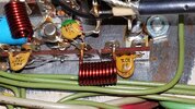
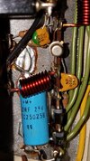
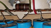
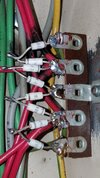
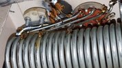
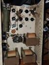
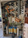
Hi guys, /gals, I appreciate any help in advance, I am good with a soldering iron and with google and I would take this amp to a certified repair guy , but the one in my area is so busy he does not reply, so all I am asking is where to start to check the circuit for trouble, history, the amp was running fine, a little low on power so I bought all nos tested 100% 6LQ6 Tubes, installed them and sizzle pop blew main power A/C fuse, so I removed all tubes, looked for damage bulging caps, burnt diodes ETC. could not find visual damage, so in goes new 30 amp A/C fuse all tubes still removed, and when powered on pop goes the fuse, so now I have checked the actual power switch to see if it went to ground when flipped on and no, nor do the wires down stream as far as I could understand how to trace, the amp does have several shady areas I could see, like wires going through a hole under the transformers with no protection, or restraint but it is so tight under transformers I cant see if any wires are making contact through frayed insulation, it appears not, I have a couple good multi meters, but I am not a tech so any next steps from a person of experience would be greatly appreciated,
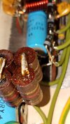
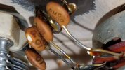
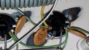
I take a lot of pictures as my eyes are not what they used to be, helps me magnify things, hoping it helps, oops also the ending 3343 jpeg pic of 2 watt what. diodes for the rectifiers circuit is my work, one blew up, causing the charred red wires behind them, the amp worked fine after the diode replacement, man did I just have an epiphany the leads to top of tubes might be touching ground, back out to check NOW! no that would be to easy still blows fuse
Ken
Attachments
-
 20220427_213536.jpg693.1 KB · Views: 281
 -
 20220427_213445.jpg529.7 KB · Views: 280
 -
 20220427_213432.jpg275.4 KB · Views: 265
 -
 20220427_213419.jpg400.3 KB · Views: 265
 -
 20220427_213343.jpg457.6 KB · Views: 259
 -
 20220427_213603.jpg343.8 KB · Views: 260
 -
 20220427_213610.jpg203.4 KB · Views: 271
 -
 20220427_213615.jpg330.9 KB · Views: 248
 -
 20220511_102312.jpg1.7 MB · Views: 267
 -
 20220511_102418.jpg2 MB · Views: 275
Last edited:
