B

You are using an out of date browser. It may not display this or other websites correctly.
You should upgrade or use an alternative browser.
You should upgrade or use an alternative browser.
-
You can now help support WorldwideDX when you shop on Amazon at no additional cost to you! Simply follow this Shop on Amazon link first and a portion of any purchase is sent to WorldwideDX to help with site costs.
-
A Winner has been chosen for the 2026 July 4th Retevis RA89R Giveaway! Click Here to see who won!
Difference in AstroPlane vs. New Top One per Eznec5
- Thread starter Marconi
- Start date

Homer, I rechecked the match and resonance for my A/P model and found the following a few mistakes in dimensions, which I fixed. I end up with resonance at 26.800 mhz. Here are my dimensions below. If you get a chance, check your antenna for dimensions and resonance and let me know how it compares.
I used the physical dimensions from my Top One to make my model, and the measurements are a little bit different from that metric takeoff of dimensions I posted some time back. I think maybe you used that metric sheet to build your model, right? They are close, but not exact.
View attachment AstroPlane Default Model.pdf
I was a little surprised that my model was so low at center frequency. I checked my real world bandwidth curves, and I note they show resonance about the same, in the area of 26.900. I was using a 50' foot feed line to test also, and that could have made a little difference.
How does your A/P resonance and match look with your analyzer? I included the Source Report that shows the match at the feed point for the model. When I set the model to resonance at 26.800 the SWR shows 1.18:1.
Booty Monster, the mast for the model is attached to the ground.
When I last had it in the air, and put the analyzer on it with the feedline around 16' long and the antenna only 15' in the air, resonance was in 10 meters. I don't remember where. I have to do it all again
When I last had it in the air, and put the analyzer on it with the feedline around 16' long and the antenna only 15' in the air, resonance was in 10 meters. I don't remember where. I have to do it all again
Then how do the measurements line up with the ones I posted?
The numbers in the green circles are what I used. The width of the top bracket worked out to 6.75" from tube center to tube center.
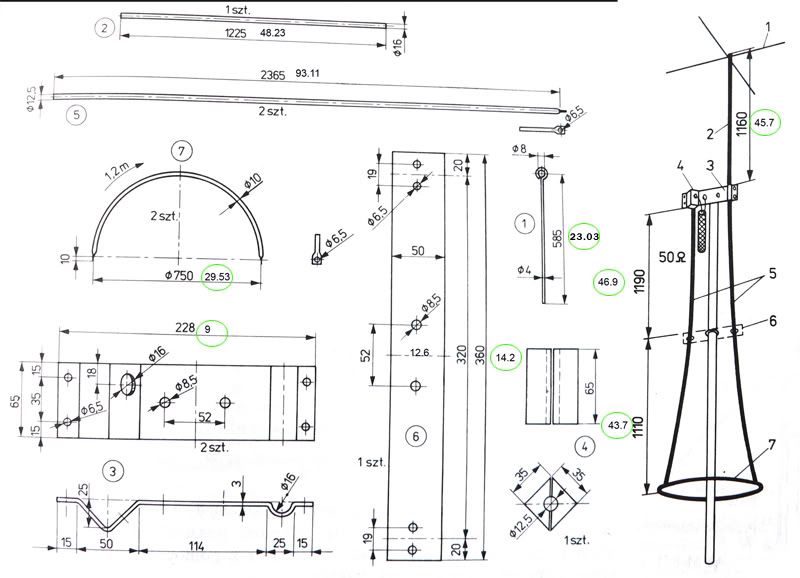
Well Homer, thanks for helping me confirm that I had the dimensions right or real close. My top bracket turns out however at only 6" compared to your 6.75". I haven't tried to change that yet, to see what happens, but I will.
I went back and redid some diameters, but we basically had almost exactly the same length dimensions, excepting my hoop is 30" vs. your 29.53", and that could make a difference too.
However, I don't think any reasonable adjustment I could make now will settle our difference in resonant frequency. I mentioned earlier that my real world bandwidth curves seemed to supported the fact that my A/P shows resonance at or near 26.800 using a feed line, so if your showing resonance up in 10 meter, then one of us has issues, and I would like to settle that if possible.
This back and forth might help me determine better if this model is even close to accurate.
BTW, after I made my adjustments to some of my diameters that were in error, I saw the resonance go down some more to 26.315, and that is going the wrong way. My model also doesn't show the bandwidth that I expected, so I have to try and figure that out too. It's always something.
Homer, as you have time, please remember and try and help me settle this issue with our difference in resonance if we can.
I have the mindset, but not the energy to do some real world testing on my Top One, the source for my A/P model's dimensions, but it has been windy here and I don't really feel good. I'll have to take my Starduster down, but that is OK, I want to reinstall my New Top One anyway...now that DX is working pretty good at times.
Here are the results after I fixed my errors. I have one model at 48' at 27.205 and another at antenna resonance of 26.315. I also lowered this model down to 16' feet just per chance to see what it might have looked like for Avanti when they checked it back in the day...considering the 20' rule of the times. It still showed a lower resonance again and the match was not good either, so I'm puzzled.
I also included the model in Free Space, and the Average Gain feature. The model shows very good results in that test for accuracy of the source. BTW the Free Space model shows a typical 1/2 wave pattern in FS for this A/P, another reason I consider it a 1/2 wave antenna. This pattern is also very similar to the one Avanti showed in their Patent. It even shows a little skew in the top high angle null, and that is all pretty convincing for me.
Average Gain is 1.015 = 0.06 db and that is pretty close to a perfect 0.00 zero.
View attachment AstroPlane default model 042912.pdf
marconi
i would have to agree with you, that the AP is acting very much like a 1/2 wave even though physically it is shorter at the top, i think i mentioned my thoughts before.
i've come to the realization that the 5/8's designation Avanti gave it was just really a name. A name that was given early on to 1/2 wave antenna's when amateurs first attempted at taking the 1/2 wave, setting it vertically at i believe 1/8 wavelength above ground and end feeding it. it was just a name, possibly the eye candy we talked about before.
i also think that by design they were very much tryingin to lower the reflection image and focus the signal on the horizon much like you alluded to earlier with the gainmaster of today.
now this having been said, i open up a can of worms and put this out...is the gainmaster really a 5/8 or just a 1/2 wave with the same characteristics shown of the AP. I know i have been a proponent of the GM being a 5/8th but this thread has really expanded my thinking.
Well gamegetter you could be right. I tend to go by the physical length and the pattern it produces. There's not much difference, but something is causing the difference we see below. If I didn't see the GM pattern stretch out a bit, and if the results looked like the 1/2 wave pattern, then I might consider the GM was nothing but a long 1/2 wave.
View attachment .50 wave vs. .625 wave.pdf
Marconi, I'll do what I can.
Things to consider:
My height above ground.
The location of my choke - 9' down from the ring.
I made it from PVC and it doesn't necessarily maintain so perfect a form as does tubing.
Things to consider:
My height above ground.
The location of my choke - 9' down from the ring.
I made it from PVC and it doesn't necessarily maintain so perfect a form as does tubing.
Well gamegetter you could be right. I tend to go by the physical length and the pattern it produces. There's not much difference, but something is causing the difference we see below. If I didn't see the GM pattern stretch out a bit, and if the results looked like the 1/2 wave pattern, then I might consider the GM was nothing but a long 1/2 wave.
View attachment 7153
i believe that this thread and your modeling has shown me one thing for sure...that is you can take a physically shorter antenna and make it behave electrically longer as seen by the pattern exhibited in your model.
perhaps the GM model u modeled is showing the pattern because of the length of 22.5' asssigned to it in the model. i am assuming this is a physical length you measured from above the choke to the end of the pvc outer pipe.
Or is that length the actual length of the wire inside the coax? just a question for the discussion.
enjoying the thread,,, have a good evening.
I made a note in my manual and it shows the top of the first coax coil to the tip is 22'4".
What do you mean, "Or is that length the actual length of the wire inside the coax?"
BTW, since I found some errors in my A/P model, I checked my New Top One model and I found several dimension errors there too. I also had my hoop too big, and the number of segment sides was wrong (and odd number) and did not space out the four legs equally on the circumference.
I have more work to do on the NTO, but I think I'll send the A/P model off to Roy Lewallen and see if he will kindly give me a critique and maybe some pointers.
Last edited:
Marconi, I went back to the AP and rescanned it with the analyzer. I have some photographic proof of my previously stated results; resonant in 10 meters.
However, taking more time than I had before I noticed there were undesirable fluctuations in the readings. I decided the antenna needed some joints re-tightened. I did. Afterward I rescanned the antenna.
I have additional photographic proof of the results. It was resonant in virtually the identical place your model says it would be. I'll share it all later if you wish.
Go figure . . .
Marconi, I went back to the AP and rescanned it with the analyzer. I have some photographic proof of my previously stated results; resonant in 10 meters.
However, taking more time than I had before I noticed there were undesirable fluctuations in the readings. I decided the antenna needed some joints re-tightened. I did. Afterward I rescanned the antenna.
I have additional photographic proof of the results. It was resonant in virtually the identical place your model says it would be. I'll share it all later if you wish.
Go figure . . .
Yes Homer please post your results. I'm just looking for the truth of this matter concerning our AstroPlanes.
Quite often I see things that click with my ideas and understanding using my models and considering my experience, but with my modeling...most often not so much. I can't predict the gain and angle for any antenna, and that is what most guys look for and want to know. With that part of my modeling, I just take what I get and report accordingly.
I found recently that some of my models will allow me to model a seemingly effective matching system based strictly on the physical appearance and dimensions. Accuracy seems to be the key to success, and that effort only works when no tuner is required or when the required tuner is inductively in series...similar to your .64 wave maybe or my Starduster. When this happens, I have expectations that the model possibly should act similar to the antenna in the real world at least regarding the match, SWR, and bandwidth. Of course I have to also consider there is usually a feed line involved in the real world testing, and that alone might be problematic regarding my getting similar results. And when all is said and done, no two installations are likely to produce the same results in real world testing, so other's mileage may vary.
So, in this case any information you have will be helpful for me. I hear a lot of bad news about modeling, it's about time for some good news, and I'm thankful whenever it happens.
Thanks for your help.
The original AP is a 3/4 wave with the lower inverse-phase 1/4 wave folded up to rephase it and the top 1/4 wave finished by using a capacitance hat.
The original objective was to produce a full 1/2 wave radiator without a lossy matching network which is usually required (for what is typically about a 2500ohm load) and with the high current node as high as possible within the FCC's 20' max above the roof limits.
If you take the 30' dia hoop and multiply it x pi then take 1/2 that (plus 1/2 the tubing circumference) for the dual current path, you'll end up with right at 48" (4') plus 7' x 2 down each side to the ring.
7' +7' = 14' + 4' = 1/2 wave (18') plus the top cap hat loaded 1/4 wave = 3/4 wave total, or the only other antenna except for a 1/4 wave which can provide right about a 50om load when driven directly.
The counterpoise is the mast.
Ingenious, really.
Am I mistaken in thinking I remember a 3/4 wave provides about 6db high-angle gain? I wonder what happens when it's lower 1/4 wave is folded back up alongside the next 1/4 wave up with an odd shape keeping the counterpoise well away from the high voltage node of the radiator?
- Marconi?
Last edited:
The original AP is a 3/4 wave with the lower inverse-phase 1/4 wave folded up to rephase it and the top 1/4 wave finished by using a capacitance hat.
The original objective was to produce a full 1/2 wave radiator without a lossy matching network which is usually required (for what is typically about a 2500ohm load) and with the high current node as high as possible within the FCC's 20' max above the roof limits.
If you take the 30' dia hoop and multiply it x pi then take 1/2 that (plus 1/2 the tubing circumference) for the dual current path, you'll end up with right at 48" (4') plus 7' x 2 down each side to the ring.
7' +7' = 14' + 4' = 1/2 wave (18') plus the top cap hat loaded 1/4 wave = 3/4 wave total, or the only other antenna except for a 1/4 wave which can provide right about a 50om load when driven directly.
The counterpoise is the mast.
Ingenious, really.
Am I mistaken in thinking I remember a 3/4 wave provides about 6db high-angle gain? I wonder what happens when it's lower 1/4 wave is folded back up alongside the next 1/4 wave up with an odd shape keeping the counterpoise well away from the high voltage node of the radiator?
- Marconi?
The math is a little to complicated for me. I would call your question the $64,000 dollar question.
I don't know about the folded idea using pi, but I use to claim the A/P was a 7/8 wave, with a 1/4 wave down, and 1/8 wave across the bottom hoop that was similar in diameter to the top hat, another 1/4 wave going up to level 1, and a 1/8 wave vertical tip with a 1/8 wave horizontal top hat.
1/4 + 1/8 + 1/4 + 1/8 + 1/8 = 7/8 wave.
Your idea is as good as mine I suppose, except I have the models below that suggest the A/P is a 1/2 wave radiator.
Here are my Free Space models in support of my idea the A/P is a 1/2 wave.
1st is your 3/4 wave with a suitable ground plane model showing just as you suggest, with high angle maximum radiation.
2nd is my model of the A/P
3rd is a 1/2 wave end fed (EF) vertical with radials
4th is a 1/2 wave center fed vertical dipole
5th is a 1/2 wave EF vertical dipole without radials
Which of these models look like the A/P?
I will have to make a model for your 3/4 with radials slanted up beside the first 1/4 wave of the radiator, and that will follow. I think it might look in FS like a Sigma4, but I don't think I remember what the S4 looks like in FS. If it looks similar to the 4 models above, then I will concede you definitely have a point to consider.
View attachment NB's idea for Astroplane.pdf
While you guys are looking at the pictures check out what happens to models with radials.
Needle Bender?
Last edited:
dxChat
- No one is chatting at the moment.