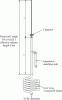
NB, it looks like your idea could have some merit. Here is a 3/4 wave with radials slanted up beside the 1st 1/4 wave of the antenna a little bit. The FS pattern looks very similar to the other four models for a 1/2 wave, but it is skewed just a little bit. I wouldn't argue the difference though. I have no problem with your idea. Is that something that you have pondered or did you get it from another source?
I also added a mast and did the model using Eznec's real Earth feature.
View attachment NB's idea for .75 wave.pdf
I also added a mast and did the model using Eznec's real Earth feature.
View attachment NB's idea for .75 wave.pdf