Hi guys. I slapped together a 3 element yagi knowing the very minimum of what I was doing.
Goal: something super light weight that I could put on top of my 11 guage telescopic flagpole
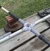
Construction materials:
Boom: aluminum painters pole
Hubs: 3/4” 4 way pvc fittings + 6-5” pieces of 3/4 pvc
Elements: cheap fiberglass telescopic fishing poles
Wire: 14AWG solid copper wire.
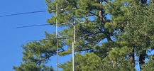
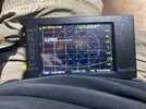
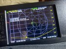
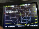
Right now it’s up about 26’ on the pole with no adjustment beyond the original cuts. It is direct feed with no matching network. Or Balun. As expected resonance is on the low side. Like 1.2/1 on 26.800 thru Channel 20 and swings up to 1.5/1 on 27.405. So it is completely usable as is. I don’t know if it was Mother Nature smiling on me but when I first got it up I made more contacts across the pond than I ever have in one day. With one station in Ireland comparing it to my Sirio 2016. Hard to quantify in actuality because of so many variables but I was pretty jazed. Needless to say.
Another reason for the goal of super light weight was so I could use an inexpensive rotor.
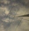
All that said I want to bring resonance higher up the band and don’t know exactly what to do. Do I just shorten the driven elements? All of them in proportion to my original cuts? Or something different like just the reflector and driven? I suspect an inch or two will be the end result but the copper wire is internal to the frame with only the tips exposed for now for tuning. So I will cut very small and be patient. Very easy up and down on that flag pole and my guess the antenna is maybe 6-7 lbs. any input appreciated!!!! Image taken it was very dark a couple of nights ago when I first pushed it up there.
Goal: something super light weight that I could put on top of my 11 guage telescopic flagpole
Construction materials:
Boom: aluminum painters pole
Hubs: 3/4” 4 way pvc fittings + 6-5” pieces of 3/4 pvc
Elements: cheap fiberglass telescopic fishing poles
Wire: 14AWG solid copper wire.
Right now it’s up about 26’ on the pole with no adjustment beyond the original cuts. It is direct feed with no matching network. Or Balun. As expected resonance is on the low side. Like 1.2/1 on 26.800 thru Channel 20 and swings up to 1.5/1 on 27.405. So it is completely usable as is. I don’t know if it was Mother Nature smiling on me but when I first got it up I made more contacts across the pond than I ever have in one day. With one station in Ireland comparing it to my Sirio 2016. Hard to quantify in actuality because of so many variables but I was pretty jazed. Needless to say.
Another reason for the goal of super light weight was so I could use an inexpensive rotor.
All that said I want to bring resonance higher up the band and don’t know exactly what to do. Do I just shorten the driven elements? All of them in proportion to my original cuts? Or something different like just the reflector and driven? I suspect an inch or two will be the end result but the copper wire is internal to the frame with only the tips exposed for now for tuning. So I will cut very small and be patient. Very easy up and down on that flag pole and my guess the antenna is maybe 6-7 lbs. any input appreciated!!!! Image taken it was very dark a couple of nights ago when I first pushed it up there.