I have seen someone post this model before, so it cannot be a totally obscure amp.
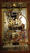
I feel it is a classic dual MRF455 type amp, so really any schematic with that transistor set will probably be close enough.
This amp has no output, the MRF455's seem ok. Nothing is visually burnt.
It was working till the owner used it on his beefed up HR2510, on SSB.
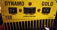
The 2510 has probably 35 to 45w SSB out. It was too much for this poor 150.
I am just trying to get it going again.
Thanks,
I feel it is a classic dual MRF455 type amp, so really any schematic with that transistor set will probably be close enough.
This amp has no output, the MRF455's seem ok. Nothing is visually burnt.
It was working till the owner used it on his beefed up HR2510, on SSB.
The 2510 has probably 35 to 45w SSB out. It was too much for this poor 150.
I am just trying to get it going again.
Thanks,