• You can now help support WorldwideDX when you shop on Amazon at no additional cost to you! Simply follow this Shop on Amazon link first and a portion of any purchase is sent to WorldwideDX to help with site costs.

End Fed 1/2 wave antenna

I am not surprised with your results. This has been the experience of countless numbers of folks for decades.
I think the questions Marconi raised were with respect to how the use of the choke worked in the scenario outlined by Bob's use of it inhis friend's situation. The most common recommendation is directly under the feed point as I believe you have done. Believe me, I am convinced of the value of the choke as a measure of control over CMC. I do not think it directly contributes to issues of TVI as normally used which makes the design of a solution such as Bob employed the matter of interest that it was/is.
Thanks for the input.

Hey Homer, what are you suggesting in your last sentence above? Is that right? What is the subject "it"?
 
Homer said:
I do not think it directly contributes to issues of TVI as normally used which makes the design of a solution such as Bob employed the matter of interest that it was/is.
it = a choke at the feedpoint

I do not think a choke used at the feedpoint directly contributes to (solving) issues of TVI as normally used. So this makes the design of a solution (utilizing a choke 18' below the feedpoint and a metal mast) such as Bob employed the matter of interest that it (subject matter) was/is.
 
I had to run a series of readings with the SWR meter because of the strange analyzer results.
I have been scratching my head over this group of reading.
Even my SWR meter promises I could talk on all bands from can to can't with a 1.5:1 or less, so I have a bit of trouble with reliability from everything right now.

SWR meter:

26.0000 -------------- 1.1:1
26.5000 -------------- 1.0:1
27.0000 -------------- 1.0:1
27.5000 -------------- 1.0:1
28.0000 -------------- 1.0:1
28.5000 -------------- 1.05:1
29.0000 -------------- 1.05:1
29.5000 -------------- 1.3:1
30.0000 -------------- 2.0:1

My meter is not bad.

I am headed back up the tower to retune the thing.

Homer, have you tried reading the Z mode, the combined complex impedance for a load?

You might also try a combination of resistors between 25/150 ohms and see what that shows you in the Z mode. The reactance should be fairly low if the resisters are non-reactive types, but when reading the Z factor for the load, it could give you a clue about what could be going on...if the meter is in question.

I know with a 50 ohm resistor on my meter I generally see about 56 ohms in the Z mode and in the impedance mode I will see a little reactance if the leads are very long. Then if it looks OK, I wouldn't worry about the meter.

Maybe give some more thought to feedline transformation.
 
Last edited:
it = a choke at the feedpoint

I do not think a choke used at the feedpoint directly contributes to (solving) issues of TVI as normally used. So this makes the design of a solution (utilizing a choke 18' below the feedpoint and a metal mast) such as Bob employed the matter of interest that it (subject matter) was/is.

I understand you were talking about a choke, but I figured you were a big believer that a suitable choke at the feed point was a safe and reliable way to help solve any TVI or CMC problems.

Sometimes I am amazed at my own confusion, but I just don't understand your words. The main word that confuses me is right off with your saying, "I do not think......." and at the end is "...was/is." To me the sentence just doesn't make sense.

Can you tell me another way so I might understand?

Have you changed your mind on the usefulness for a coax choke at the feed point?
 
No I have not changed my mind about the usefulness of a choke at the feedpoint for controlling CMC.
I am not convinced that a choke at the feedpoint does anything at all for TVI.

As you know, CMC is a RF issue from the feedline. TVI is a problem not limited to the feedline, but may be RF from the antenna. If it is from the antenna then a choke beneath the antenna won't do any good for controlling that TVI.

Bob's solution of utilizing a choke 18' below the feedpoint and a metal mast made the subject about controlling TVI and CMC the matter of interest that it was before, and still is. It is a different design than the traditional choke at the antenna feedpoint, and is worth further study.
 
  • Like
Reactions: 1 person
I had to run a series of readings with the SWR meter because of the strange analyzer results.
I have been scratching my head over this group of reading.
Even my SWR meter promises I could talk on all bands from can to can't with a 1.5:1 or less, so I have a bit of trouble with reliability from everything right now.

SWR meter:

26.0000 -------------- 1.1:1
26.5000 -------------- 1.0:1
27.0000 -------------- 1.0:1
27.5000 -------------- 1.0:1
28.0000 -------------- 1.0:1
28.5000 -------------- 1.05:1
29.0000 -------------- 1.05:1
29.5000 -------------- 1.3:1
30.0000 -------------- 2.0:1

My meter is not bad.

I am headed back up the tower to retune the thing.

I can't say it is not possible with an inline SWR meter to see such low SWR readings over what now is likely over 6 mhz, but I just don't believe that can be right for such an antenna.

Even my A99 shows a wide bandwidth, but it get a lot of heat from experts on the matter...for having a very lossy matching system in order to see that wide of bandwidth.

Could this mean, since your antenna is almost double the bandwidth that suggest your antenna has even more losses than my A99? I understand that DX contacts are a lot different that line of sight local work, but I didn't suspect your antenna was rife with losses the other day when you and I were talking on-air. I agree with you this is really confusing.
 
No I have not changed my mind about the usefulness of a choke at the feedpoint for controlling CMC.
I am not convinced that a choke at the feedpoint does anything at all for TVI.

As you know, CMC is a RF issue from the feedline. TVI is a problem not limited to the feedline, but may be RF from the antenna. If from the antenna then a choke beneath the antenna won't do any good.

Bob's solution of utilizing a choke 18' below the feedpoint and a metal mast made the subject about controlling TVI and CMC the matter of interest that it was before, and still is. It is a different design than the traditional choke at the antenna feedpoint, and is worth further study.

I agree with this, and I posted the same the other day posting to Jo. I just wasn't getting the distinction you were trying to make, heck I could have been doing the same thing to her.
 
I went back to the antenna and readjusted the length, reset the cap to its middle capacitance, and re-tapped the coil for the lowest SWR. I then moved the cap in both directions looking for the lowest r/x readings. I also took some readings in the Z mode, as Marconi suggested.
The antenna's length is now 17' 7/8"
Of interest to you, Marconi, is that I can move the antenna's length - as much as 6" shorter now - and retune it with the variable cap I made. This cap is made of two pieces of aluminum flat bar stock separated by a foam type double sticky tape dielectric stuck to only one of the flat bars.

The antenna was measured with an electrical halfwave coax at 21' and 28.5' above the earth.

17_78.jpg


p0013.jpg
 
I know with a 50 ohm resistor on my meter I generally see about 56 ohms in the Z mode and in the impedance mode I will see a little reactance if the leads are very long. Then if it looks OK, I wouldn't worry about the meter.
I put a 50 resistor load on the analyzer.

In Z mode it reads
SWR 1.0
Z=56
θ=0


Regular and Resonance modes both read

SWR 1.0
R=56
X=0


So I guess I'll quit worrying about the analyzer. On the feedline in the shack and got a regular mode and a Z mode measurement on the antenna:

---------Regular ------------------------------- Z mode -------

2.0 ----29.300 R=27 X=6 ---------------29.308 Z=29 θ=0

1.5 ----28.440 R=65 X=21 --------------28.474 Z=66 θ=0
1.5 ----28.305 R=76 X=0 ---------------28.992 Z=77 θ=0
1.0 ----27.482 R=71 X=0 ---------------27.480 Z=69 θ=0
1.0 ----27.405 R=68 X=0 ---------------29.400 Z=65 θ=0
1.0 ----27.185 R=64 X=0 ---------------27.185 Z=61 θ=0
1.0 ----27.023 R=62 X=0 ---------------27.016 Z=59 θ=0
1.1 ----26.965 R=61 X=0 ---------------26.965 Z=60 θ=0
1.5 ----26.197 R=107 X=0 --------------26.166 Z=98 θ=0
2.0 ----25.164 R=69 X=19 --------------25.125 Z=71 θ=0

Maybe give some more thought to feedline transformation.

What are your recommendations for this?

BTW, in the above post above the photo of the antenna where it reads

25.805

it should read

28.805
 
I put a 50 resistor load on the analyzer.

In Z mode it reads
SWR 1.0
Z=56
θ=0

Regular and Resonance modes both read

SWR 1.0
R=56
X=0

So I guess I'll quit worrying about the analyzer. On the feedline in the shack and got a regular mode and a Z mode measurement on the antenna:

---------Regular ------------------------------- Z mode -------

2.0 ----29.300 R=27 X=6 ---------------29.308 Z=29 θ=0
1.5 ----28.440 R=65 X=21 --------------28.474 Z=66 θ=0
1.5 ----28.305 R=76 X=0 ---------------28.992 Z=77 θ=0
1.0 ----27.482 R=71 X=0 ---------------27.480 Z=69 θ=0
1.0 ----27.405 R=68 X=0 ---------------29.400 Z=65 θ=0
1.0 ----27.185 R=64 X=0 ---------------27.185 Z=61 θ=0
1.0 ----27.023 R=62 X=0 ---------------27.016 Z=59 θ=0
1.1 ----26.965 R=61 X=0 ---------------26.965 Z=60 θ=0
1.5 ----26.197 R=107 X=0 --------------26.166 Z=98 θ=0
2.0 ----25.164 R=69 X=19 --------------25.125 Z=71 θ=0


What are your recommendations for this?

BTW, in the above post above the photo of the antenna where it reads

25.805

it should read

28.805

Regarding the transformation idea. I have an opinion, but again it flies in the face of the common wisdom about jumper length, tuned jumpers, 1/2 wave resonant jumpers, and 1/2 wave multiples for feed line length, but all that will happen in such a discussion is a rash of protest and arguments, so I ain't touching that idea here. This CB idea is so entrenched in the idea of a proper line length theory, that for me a sensible discussion on that issue is just not fruitful.

Now, could I be wrong in my idea in this regard, of course, but I have never had a good discussion...that either changed my mind or changed the thinking of others on the subject. So what is the point.

My best advice is to always test at the feed point when possible and then try and duplicate those results any other way that can be imagined, and then compare the results. I think in theory there is a way to use a feed line and then expect to produce exacting results, but the reactance at the load always has to be considered to be the fly in the ointment.

Transformation is a difficult concept to put into words, and makes for a lot of complicated implications when trying to physically measure accurately the feed point impedance with the tools available to us as CB operators. If there could be a good and convincing argument made in a sensible discussion, I surely could change my mind however.

Does transformational affects make any real difference in the end, I'm not sure. I just know efforts at trying to measure feed point impedance can develop to be like chasing your tail, and I figure most operators just ignore the issue and claim what they see, right or wrong.

You can read the words in my signature area, where I consider the idea for feedline transformational affects...to be buried within that meaning somewhere.
 
Last edited:
Homer don't let my previous post confuse the issue. Since you tested your meter and find that you are not that far off, then I assume your analyzer numbers are probably pretty close.
 
As I had told some I was to do, I once again went back to the antenna.
I had suspicions regarding the way things were going with the MFJ-259b readings.

I did several things in order to be sure of my controls on this antenna.

1. I took a continuity tester and sampled different ones of the radials. What I found was that some were not well connected

in the system. I had a fix.

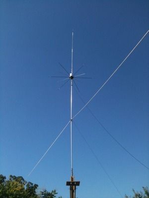
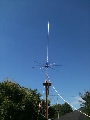
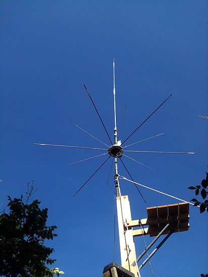
2. I replaced 6 of the 12 three feet long radials with 6 fifty-nine inch radials. Common wisdom states that the radials

need to be at least 1/8 wavelength to be effective. I now had 6 x 3' and 6 x 5' radials for my GP. To cure the issue with

some of the radials not having good grind to the system I ran an additional wire around the entire thing and checked

continuity. All of them were now firmly in the system.

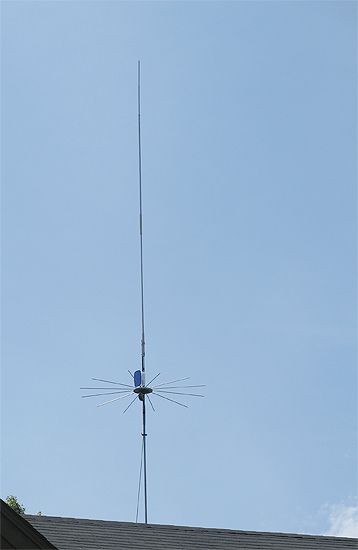
3. I now attached my analyzer directly to the feedpoint using two female threaded couplers and a single double male

threaded coupler. This gave me the reach through the GP to the SO-239 on the antenna. This was done standing on the tunng

platform of my tower with the antenna feedpoint at 21' height above the ground.

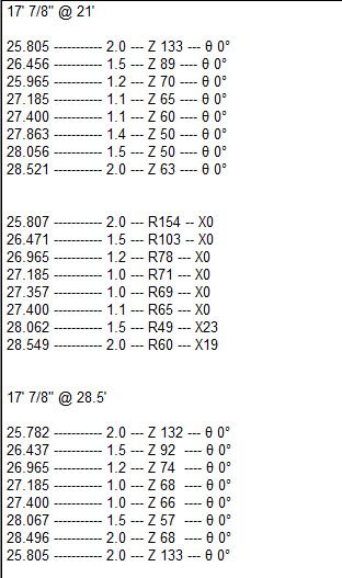
4. I then went into the shack and took a series of analyzer readings through the feedline at antenna FP height 21'

5. Lastly, I raised the antenna FP to 37' and took another series of analyzer readings from the shack end of the feedline.

Results below.

I measured the bandwidth as the matching network had been set before modifications to the radials at 21' height:

SWR ---------- Freq ------ X ---- 0

2.0 --------- 28.766 ---- 55 ---- 18
1.5 --------- 28.358 ---- 49 ---- 23
1.1 --------- 27.549 ---- 57 ---- 1
1.2 --------- 27.405 ---- 59 ---- 5
1.3 --------- 27.185 ---- 64 ---- 11
1.5 --------- 26.951 ---- 68 ---- 19
2.0 --------- 26.455 ---- 85 ---- 17

Moved the tap point on the coil to try to center on 27.400

2.0 --------- 28.449 ---- 65 ---- 18
1.5 --------- 28.035 ---- 48 ---- 22
1.0 --------- 27.395 ---- 59 ---- 0
1.1 --------- 27.185 ---- 63 ---- 0
1.5 --------- 26.727 ---- 73 ---- 14
2.0 --------- 26.324 ---- 85 ---- 22

I had the center where I wanted it, but I didn't want to have
the bandwidth so low, so I adjusted the variable aluminum flat bar capacitor.


2.0 --------- 28.907 ---- 55 ---- 18
1.5 --------- 28.444 ---- 48 ---- 22
1.2 --------- 28.027 ---- 49 ---- 9
1.3 --------- 27.406 ---- 60 ---- 10
1.5 --------- 27.086 ---- 67 ---- 20
2.0 --------- 26.554 ---- 86 ---- 17


Results from the feedline in the Shack at 21' height.

2.0 --------- 29.552 ---- 25 ---- 4
1.5 --------- 28.652 ---- 52 ---- 23
1.1 --------- 27.405 ---- 50 ---- 7
1.1 --------- 27.185 ---- 46 ---- 7
1.2 --------- 26.965 ---- 45 ---- 9
1.5 --------- 26.359 ---- 61 ---- 22
2.0 --------- 25.586 ---- 136 ---- 0

Results from the shack end of feedline at 37' height

2.0 --------- 29.572 ---- 25 ---- 4
1.5 --------- 28.699 ---- 49 ---- 23
1.1 --------- 27.405 ---- 50 ---- 8
1.1 --------- 27.185 ---- 45 ---- 7
1.2 --------- 26.965 ---- 44 ---- 9
1.5 --------- 26.351 ---- 62 ---- 22
2.0 --------- 25.518 ---- 130 --- 0

photo4.jpg
photo5.jpg

 
Marconi,
here are my thoughts on the 21' and 37' readings from the shack, everything else between the two readings unchanged. I speculate that the counterpoise is indeed effective on the halfwave if for no other reason but to decouple it from earth, and if so it would reduce losses to ground sometimes associated with a lack of artificial counterpoise. I think that the virtual sameness in the measurements indicates the effectiveness of the GP. So, end fed half wave antennas may very well benefit from a counterpoise/groundplane . . .

newrad3.jpg
 
  • Like
Reactions: 2 people

dxChat
Help Users
  • No one is chatting at the moment.