• You can now help support WorldwideDX when you shop on Amazon at no additional cost to you! Simply follow this Shop on Amazon link first and a portion of any purchase is sent to WorldwideDX to help with site costs.

End Fed 1/2 wave antenna

For the record here is a list of the analyzer readings in the shack using about 84' of RG8/u coax:

2.0 ------------------- 29.288 ---- R27 --- X5
2.0 ------------------- 29.160 ---- R28 --- X9
1.5 ------------------- 28.485 ---- R55 --- X23
1.4 ------------------- 28.210 ---- R71 --- X0
1.0 ------------------- 27.523 ---- R70 --- X0
1.0 ------------------- 27.405 ---- R60 --- X0
1.0 ------------------- 27.089 ---- R60 --- X0
1.1 ------------------- 27.062 ---- R58 --- X0
1.5 ------------------- 26.283 ---- R98 --- X0
2.0 ------------------- 25.507 ---- R120 -- X0
2.0 ------------------- 25.401 ---- R101 -- X7

Wildest readings I've ever seen from a 259B. With 70Ω your SWR should read 1.4:1 not 1:1, and to have an X=0 over so wide a range is stunning!

Interestingly, your coax is cut to right about 3.5 wavelengths x VF @ .66

I just might need to get detailed plans for that one! :w00t:
 
Well, you have voiced a consternation for me. Why it is reading as it is. However, it reads differently at times . . . notice this one

1.1 ------------------- 27.062 ---- R58 --- X0.

It seems pretty much in line with what I'd expect. . . . yet . . .
 
So it seems. There are two or three local stations from 15 to 20 miles or so that are like digging out from the dirt on a 5/8 antenna. I have to listen for them to get on the air to make a comparison. Encouragingly, today Rhett_RT307 was out locally in a rental car and I had a great copy from him on the 1/2 wave antenna. There seemed to be better response from it to the area he was in than I tylocally get from my GP mounted 5/8 wave. Again, further observations of contacts wili tell more.

Just to qualify, I was running a Magnum 257HP that does about 75 watts out, on a Wilson 500 mag mount, dead center in the roof of a Toyota Rav4. Who is Rhett? :blink: I don't think he gives a damn. lol

BTW, I could hear you all the way in Fayetteville clear as a bell.

73 from Brett RT307

ps great to see you again, my friend!
 
Sorry about the mangling of your name, Brett. By the time I noticed I couldn't edit it.

Yep, it was great to see you again. I enjoyed the supper, too! The friendship was better, though.
 
  • Like
Reactions: 1 person
Until I have a solid way of measuring/observing the differences between known stations it will be hard to answer all your questions.
I did not use the variable cap very long, and when I did I had it static. Rotating it away from fully open resulted in a severe mismatch.
Unless I come up with a smaller variable than I have, make one/buy one I won't rightly know.
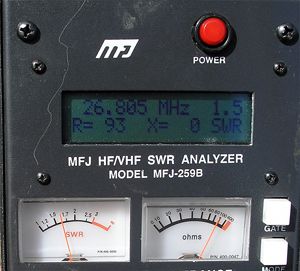
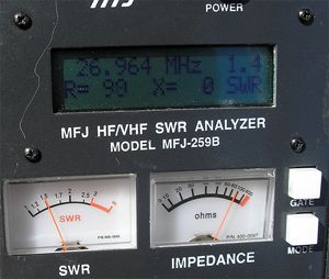
What we see on the analyzer is still open for interpretation it seems.
To get the match down from around 1:3 to one to 1.0:1 on 27.405 I had to shorten the antenna 1-1/2". The new matching network and the radials may have contributed to this difference. What I'd have to do is remove the GP and see where the tune landed afterward compared to now.
The comparison to the antenna with the previous matching network has too many dissimilarities to be a reliable reference, IMNotSoHO.
I had a match previous to the GP with this network, however I didn't record it.
I have not read whether anyone retuned their antennas after the addition of the spiderplane, either so we have no point of reference to the effects of the spiderplane on the match. As for creating the swastika thing I could always hang a picture of Adolf Hitler in the shack and see if that will help. Just kidding. I could add wires to the ends of the radials at 90 degrees.

Homer, I assume you might be talking about my questions, but I'm not sure.

Are you telling us now that you don't have any previous signal test results to use in comparing your future real world results for this EFHW?

Am I right or wrong, that your use of the variable cap did not work out to effectively control the match except in a static and open position?

I think I recall you were impressed with a video of a guy using a variable cap to tune something, and maybe that gave you the idea to do that with this EFHW. But, are you telling us now that the cap you used did not work out as you expected, and the rotation of the fins had to be set wide apart in order to work at all, and it only worked a little bit when it was set and static in that open position?

These are just some comments.

1. It would seem to me changing both the tuning device and adding the 12 x 36" radials in one step...would likely leave questions as to what did what, and I agree trying to compare results under such circumstances would be questionable, but you did get nearly...the same'O same'O, so no harm done.

2. I don't understand all the X=0 values either, just like NB suggested. But, I think it is clear that your analyzer shows us, that basically, no mater what you do to the antenna, radials or not, we don't see the effects of much change...in the match at least. Again, that is what my observations have been showing for a long time. However, I can't make anymore out this seeming fact, than maybe we see a bit less bandwidth with radials added, and maybe the bandwidth curve takes a more traditional bowl shape...when radials are attached.

3. Concerning the lack of whether others had to re-tune their EFHW after adding radials...whether spiderwave, original, or 1/4 wave should not be in dispute...if your results and mine are correct. IMO, according to both of our real world results...adding radials doesn't seem to present a problem that might require retuning of an EFHW if matched well to start.

4. I think Bob's design was using 3 radials that were maybe 72" radials from a Solarcon GPK, but I can't be sure. I think maybe they were using an all metal type EFHW, so unless he is willing to tell us the dimensions, I could only guess. I did a model once, and posted it to this forum, but I don't recall, when I asked him if it looked like his antenna...whether he ever confirmed or denied that the model of dimensions were similar to his project. I think they used wire and twine to help secure the added wire portion of the radials horizontally.

Homer, maybe this spiderplane idea is the missing link we haven't considered in seeing an EFHW that can produce a better gain pattern by 2-4 dbi, much less 2-4 Sunits like has been claimed. Honestly, I could never tell a difference in signals.
 
Last edited:
Well, you have voiced a consternation for me. Why it is reading as it is. However, it reads differently at times . . . notice this one

1.1 ------------------- 27.062 ---- R58 --- X0.

It seems pretty much in line with what I'd expect. . . . yet . . .

Well, according to my precise miscalculations ;) Your 1/2 wave radiator should be 17' 5" @ 27.2mhz or 17' 6" @ 27.062mhz.

That's factoring in an average of .825" diameter.

Is it close?
 
Nb,
Yes. The length of the radiator is exactly 17' 7" as measured when I adjusted the length for a match 6/4/2012 when I put the radials on it on 6/4/12.
 
Homer, I assume you might be talking about my questions, but I'm not sure.
Yes I am.
Are you telling us now that you don't have any previous signal test results to use in comparing your future real world results for this EFHW?
I have none seeing that reliable data other than my DX contacts isn't available. The locals are DX shy and pull their heads into their shells when skip rolls.
Am I right or wrong, that your use of the variable cap did not work out to effectively control the match except in a static and open position?
That is correct. I immediately made the CD cap on that account.
I think I recall you were impressed with a video of a guy using a variable cap to tune something, and maybe that gave you the idea to do that with this EFHW. But, are you telling us now that the cap you used did not work out as you expected, and the rotation of the fins had to be set wide apart in order to work at all, and it only worked a little bit when it was set and static in that open position?
YEs, but it was a set of photos and some comments on the project that nudged me to give the project a try. Once started I just moved to the other two homebrew caps I've employed. Eithoer of them a variable, too, but when once my match is set my antenna being for a single band I do not move it from its set point. It is true about the wide open setting for the originals VC.
These are just some comments.

1. It would seem to me changing both the tuning device and adding the 12 x 36" radials in one step...would likely leave questions as to what did what, and I agree trying to compare results under such circumstances would be questionable, but you did get nearly...the same'O same'O, so no harm done.
Other than bandwidth changes, and a tendency of the analyzer to read more resistive value on the match. . . . nope.
2. I don't understand all the X=0 values either, just like NB suggested. But, I think it is clear that your analyzer shows us, that basically, no mater what you do to the antenna, radials or not, we don't see the effects of much change...in the match at least. Again, that is what my observations have been showing for a long time. However, I can't make anymore out this seeming fact, than maybe we see a bit less bandwidth with radials added, and maybe the bandwidth curve takes a more traditional bowl shape...when radials are attached.
My thought, too.
3. Concerning the lack of whether others had to re-tune their EFHW after adding radials...whether spiderwave, original, or 1/4 wave should not be in dispute...if your results and mine are correct. IMO, according to both of our real world results...adding radials doesn't seem to present a problem that might require retuning of an EFHW if matched well to start.
I will see where the tuning falls when I remove the radials. That I can easily assess.
4. I think Bob's design was using 3 radials that were maybe 72" radials from a Solarcon GPK, but I can't be sure. I think maybe they were using an all metal type EFHW, so unless he is willing to tell us the dimensions, I could only guess. I did a model once, and posted it to this forum, but I don't recall, when I asked him if it looked like his antenna...whether he ever confirmed or denied that the model of dimensions were similar to his project. I think they used wire and twine to help secure the added wire portion of the radials horizontally.
I haven't been able to google up more than three or four references to a spiderplane so far, and no photos. Not sure of its dimensions at all.
Homer, maybe this spiderplane idea is the missing link we haven't considered in seeing an EFHW that can produce a better gain pattern by 2-4 dbi, much less 2-4 Sunits like has been claimed. Honestly, I could never tell a difference in signals.
Only Jesus knows that for sure, and he seems to be keeping it close to his chest sharing it only with his main man, Bob.
 
Nb,
Yes. The length of the radiator is exactly 17' 7" as measured when I adjusted the length for a match 6/4/2012 when I put the radials on it on 6/4/12.

Is that measured from the point of feed?

What's it look like at 26.925?

On what frequency do you find absolute center of tuning?

What's the radiator diameter at both the bottom & the top?

I can't stand being off by an inch!! :sad:


;)
 
like i said... the cmc has all stopped after the coil was introduced

that my findings anyway.

jo

I am not surprised with your results. This has been the experience of countless numbers of folks for decades.
I think the questions Marconi raised were with respect to how the use of the choke worked in the scenario outlined by Bob's use of it inhis friend's situation. The most common recommendation is directly under the feed point as I believe you have done. Believe me, I am convinced of the value of the choke as a measure of control over CMC. I do not think it directly contributes to issues of TVI as normally used which makes the design of a solution such as Bob employed the matter of interest that it was/is.
Thanks for the input.
 
Is that measured from the point of feed?

What's it look like at 26.925?

On what frequency do you find absolute center of tuning?

What's the radiator diameter at both the bottom & the top?

I can't stand being off by an inch!! :sad:


;)

NB, you can't stand being off by a .03125", and sometimes I find that difference in my models makes all the difference.

Personally, I think that Homer's EFHW length is controlled by his use of the cap, fixed or not.

I suggested earlier that maybe he could, within reason, adjust the antenna length over varied lengths and then use the VC to adjust out the reactance, but I'm not sure what he told me earlier, when I asked him about his adjusting his variable capacitor.

On the other hand NB, I find out now for sure...that VC didn't work out as expected. So, we still can't tell for sure what might really happen with the overall length when Homer is using a variable capacitor. That might mess up your length idea, regardless of the diameter.

Good work Homer. My poor wifey use to just ignore me when I was acting crazy working on some old antenna, and she just got the room smell good spray out...when the antenna crazies showed up. (y)
 
Is that measured from the point of feed?

What's it look like at 26.925?
Don't know without remeasuring on that frequency, but these two photos were in that area as read from a electrical 1/2 wave jumper. I can not directly hook the analyzer to it with the radials attached.

P0015a.jpg


P0016a.jpg

On what frequency do you find absolute center of tuning?
All I can tell you is look at readings from the shack and look at the photos taken from close to the feedpoint and draw your own conclusion on this one. I am going to have to revisit the antenna for more tuning if you ask me . . . or else send the analyzer in for recalibration. Looks weird to me.

What's the radiator diameter at both the bottom & the top?

I can't stand being off by an inch!! :sad:


;)

1/2" Remember, this one is a re-utilization of a dipole. The middle 16' would be 5/8".
 
Last edited:

dxChat
Help Users
  • No one is chatting at the moment.