• You can now help support WorldwideDX when you shop on Amazon at no additional cost to you! Simply follow this Shop on Amazon link first and a portion of any purchase is sent to WorldwideDX to help with site costs.

EPT360015C Connex cx3400hp dual mosfet issue.

Couldn't have done it without you being there to help Andy. The way you detail things helps more than you know. You're not spoonfeeding, you're educating others in the process.

I've informed the owner and he's excited to get it back. I did finally ask him why the connection to this specific radio and he told me his dad bought it for him before he passed. I think I made the right decision in not charging him for this. He's truly a good kid (kid to me, lol).

With the upgraded regulators and proper ma, volts, etc...this radio should last him a while. I know it's not perfect, but it's back from the closet of death, lol...

Now, I can jump back on the superstar 3900 with the same board. I think I have another thread on this site for that radio.

The guy wanted me to tell you again Andy, thank you, thank you and God Bless you. And I feel the same Andy, thank you for being so kind, patient and helpful.
 
  • Like
Reactions: NZ8N
Well Andy, I did a stress test on it last night to check for a decrease in output wattage, overheating and stability. Below is the results.

Deadkey test result (10w carrier) - 7 minutes of deadkey before am regulator got pretty hot.

Cooldown test result - 2.5 minutes to return to idle temperature.

Audio test result - 8 minutes of constant audio swing at 60+ watts (yes I got more out of it) before am regulator got pretty hot.

Mosfets stayed cool to warm during the entire process.

All other components stayed cool to warm the entire process.

No decrease in output power, no fluctuating of output power.

I'd say DONE, what do you say Andy?
 
Well, 7 minutes although seems short for some - this also helps to know the 8 minutes result too.

This actually is normal - the TIP36C is about the only part that can survive the beating - others can maybe last under longer time frames - but a lot of this is dissipation as a volt/watt per volt drop issue WITH any sort of AM regulator. Lessening the Wattage is one factor - but not the only saving grace.

Some of the others means putting the limiter back to work in the radio - and you can hear the "Aww's" in the crowd from that approach.

Only other thing would be to use smaller values for C190 - the 100uF to a 68 or 47uF value might reduce the swing hence the linear drop and load swings that make linear device heat up. Changes the bandwidth too - not many might like the sounds it makes from that

And although many would say "try max mod" well, that part and the one you're using are about dead-even when it comes to survivability in such a chassis - again, just about anything lives longer with less swing demands on the power rails to the parts.

The problem is voice and it's dynamics - takes their tolls on linear power delivery systems - it's a requirement for AM - SSB and FM not so much for they are "low level" both use "deviation" to a degree and one uses the dynamics of the envelope but for only one portion (Side band information) and that is done at low-level signal processing. Deviation is a bandwidth or how much shift in frequency occurs, which places the power demands on the TIP36C in a different light but it affects frequency range of signal transmitted at a given carrier level.

It means putting back in the limiter AMC control in control and stuff like that - but that is a personal choice for the end user. Not everyone is like me, in that; I use limiters and only found ways around some performance hits they're notorious for. And EVEN WHEN Limiters are in place, the "tricks" used to limit their "limits" and how they impact the audio signal - you're still going to have heating issues with the AM Regulator.

But most of all, if the customer is happy, that is all that matters. :)
 
Yes, I did put the AMC back in. I had mentioned the exact same thing to him about a month ago and he was fine with me putting it back in. I put in a c945, same as most AMC transistors. I put it in after I got done with everything and then retuned. The output power now is around 51 watts peak (after I retuned the last time with limiter out I got around 65+ watts peak, but then I put amc back in and it dropped). Internal carrier adjustment I replaced with another of the same value, but of the standard type also.

All the above made a world of difference, as you stated it would. He's very happy.

I did not change the value of c190 as you suggested though. Should I have?
 
IF C190 is the typical "100uf - 50V" then no, you don't need to change it unless it is bulging or otherwise the top of the caps can, those score marks - are perforated open.

upload_2021-12-2_18-42-44.png
upload_2021-12-2_18-43-59.png

The above are just some examples of GASSING types of Electrolytics or otherwise "shocked" caps that have failed.

So, if the radio seems ok, and the age of the radio doesn't seem "old" as some older equipment -then no, you should give it back to the customer.

However - scratchy knob turning or knobs that feel hard or heavy to turn - might indicate some age has set in and their bearings, shafts and composition needs to have some TLC.

If you want, you can segue over to this site to know more about these events...
https://www.robotroom.com/Faulty-Capacitors-1.html

The C190 cap does get a workout - and many radios can benefit with regular Maintenace of such things - at least the cap itself is current limited but will see quite a wide variety of voltage swing on its leads during its lifetime. It really acts like a low-pass filter that also provides the DC bias "tank" the radio generates it's AM Envelope from - the pool or reserve for the window of operation the fill and drain the cap thru the filter network around it performs.

When you change the value of the cap in Farads - the level or rate of charge and discharge changes - so that changes the "window" the AM Regulator operates in.

Once you get comfortable with working around these circuits, you might want to investigate some other reasons why the values used, are the ones they stayed with...

You can change the way the audio sounds - by changing the cap - but also you can change the NUMBER of caps used.

upload_2021-12-2_19-28-46.png

You know you have 100uF as pretty much the "standard" - but you can also apply this same 100uF by using combinations of the various cap values to obtain this value or close to it.
  • - in doing so, also changes some areas of the audio spectrum the radio processes thru the AM Regulator. In certain vocal ranges of audio - some capacitors make a microphone sound better or "sharper" than using the 100uF on its own.
I'll let you play with that as you get more acquainted with AM Regulator systems like what the Connex Galaxy and Range / RCI use.
 
Last edited:
  • Like
Reactions: tecnicoloco
Wow, I was listening on the radio last night and I heard the owner on this connex. Everyone gave him high marks on the loudness but clarity of this radio. I was even astonished at how clean but yet loud this thang was. Everyone kept asking him who did it and he finally told them, wow, you could have heard a pin drop due to the silence.

The owner contacted me and told me thank you again for fixing his baby. I told him all the credit goes to Handy Andy for helping me out.

Thanks again Andy, this radio is kicking butt out there.
I have read this rather large post and I can surely identify with the difficulty of repairing this particular radio. I have one on my bench that I was trying to look at for a friend blown finals and all. I have no experience at repairing radios so I was quite excited to see such a detailed post about the process. I have no modulation and I got as far a being able to hookup all but the last mosfet. That’s when power drops to nothing and AM regulator gets hot. I wish I could find a schematic. I’m using a Galaxy 33 but it’s slightly different. It’s so much work to fix a simple CB. It seems like it’s way over engineered. Why this radio is so finicky with draw and voltage. Man it’s a nightmare! But I keep coming back for more. I’ve learned a lot but not enough yet. One thing I’d like to clear up is when checking voltage at the gates you check from gate pad to source with legs lifted? And where do I measure voltage at the am regulator. Do they mean when I turn the AM trimmer that the center pad should change voltage? I’m stumped
 
  • Like
Reactions: Eldorado828
Welcome.

Do the following with a dummy load on the antenna connector.

For Gate voltage - measure from Pad to Foil ground.

For Gate mA reading (Recommended)
  • - remember to set the RF POWER to max and unjumper or unsolder the legs of the MOSFET upstream (example - measuring Final - remove/lift legs of DRIVER to keep it from sending power skewing measurement)
  • then place radio in SSB mode or FM mode RX - Max RF power
  • Measure mA from Jumper that goes to AM Regulator - as your RED lead
  • and Black Lead to jumper that goes to part (the middle leg or Drain - Collector if Bipolar).
  • Locate trimmer that corresponds to the part you're adjusting bias for
  • Put radio in TX mode no audio
  • Set meter for 200mA
  • adjust mA using trimmer until it meets specs state in manual or if you're doing this without one, usually 50mA MAX power draw is usually sufficient.
  • if there are other parts needing trim, repeat above steps - else remove meter and reinstall jumpers - resolder legs of parts removed or disconnected - verify operation.
This jumper is the TP8, 9 etc?
 
Yes, those TP's are:

Furthest to the right towards AM Regulator - RED lead of ammeter.
The other two?
Furthest to the LEFT - Driver.
Middle one is FINAL.

1649015511614.png

You measure RF power by voltage present at the AM Regulator pin, so SSB mode, RF POWER MAX, then it should be measured from TP to ground shows ~12~13.8V - so this is how you verify you have the proper mA to power test ratio - you make sure you have full battery voltage going to the test points, and then test and set mA using ammeter for proper mA drive bias.

In SSB modes, with no audio - you don't see RF power - but you do need to have the full voltage to the rails if and when you do the bias adjustment.

If you can understand that procedure - you're pretty much halfway home - but this procedure below is for radios that have no jumpers just bias trimmers and no way of knowing otherwise...
1649006277492.png
In a Galaxy radio circa EPT3600 series - you don't have "W" you have TP - so the above is to help those best guess the mA draw using the trimmers and just test mA draw thru the power leads.

Simple enough, but many get blown away unless you know and can formulate a process of understanding it ahead of time then the process goes very quickly and no jumpers have ever even need to be removed even in the older units.
 
Last edited:
  • Like
Reactions: Shadetree Mechanic
Yes, those TP's are:

Furthest to the right towards AM Regulator - RED lead of ammeter.
The other two?
Furthest to the LEFT - Driver.
Middle one is FINAL.


You measure RF power by voltage present at the AM Regulator pin, so SSB mode, RF POWER MAX, then it should be measured from TP to ground shows ~12~13.8V - so this is how you verify you have the proper mA to power test ratio - you make sure you have full battery voltage going to the test points, and then test and set mA using ammeter for proper mA drive bias.

In SSB modes, with no audio - you don't see RF power - but you do need to have the full voltage to the rails if and when you do the bias adjustment.

If you can understand that procedure - you're pretty much halfway home - but this procedure below is for radios that have no jumpers just bias trimmers and no way of knowing otherwise...
View attachment 58279
In a Galaxy radio circa EPT3600 series - you don't have "W" you have TP - so the above is to help those best guess the mA draw using the trimmers and just test mA draw thru the power leads.

Simple enough, but many get blown away unless you know and can formulate a process of understanding it ahead of time then the process goes very quickly and no jumpers have ever even need to be removed even in the older units.
Well I have a better understanding of where to check for mA draw. That pic is where i set mA for my Galaxy 88, I'm working on a Connex 3400 HP mosfet version with the 360015C board. I started out with no power or modulation, then I installed new IRF520s and i got power on High and low but no modulation on low. I noticed the regulator getting real hot so I unhooked everything and installed a amp meter on the power cord I get .250 amps draw unkeyed, then when I key it goes to .45 or so.I set gate voltage real low at first 1.5 volts then hooked up the driver transistor and checked the power draw, it was less than 1 amp about .75. Regulator was not getting hot. I checked gate voltage at first final and set it to 1.5 volts and hooked it up. I was able to adjust watts to 10 watts but backed it down to 1 watt just to test. I then checked the last final and set the gate to 1.5 and I noticed no output and regulator getting hot. I unhooked final and tried finding out why this would happen. Somwhere along the line I lost modulation totally. Without a schematic i've been taking wild guesses and checking components for opens or shorts but no luck. So I went back and started all over again trying to follow your instructions but I am getting lost somewhere. If only you could make a youtube video my brain might be able to follow without burning so many cells. It would help many folks with one stroke compared to helping one guy at a time. I really am trying to learn and have learned alot but it seems overwhelming sometimes, especially with no training or schematics.
 

Attachments

  • Connex.jpg
    Connex.jpg
    2.3 MB · Views: 7
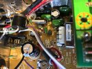
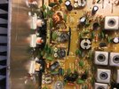
  • Connex finals.jpg
    Connex finals.jpg
    2.5 MB · Views: 7
Last edited:
When the Regulator is getting hot - and no parts are even connected to the Test points - then stop - you have a bigger problem - you would have also blown the Ammeters own internal fuse in the process protecting some of the work - but not what is happening at the AM Regulator.

Does the radio have any mods done - like NPC a diode oriented backwards on the foil side? - these can blow shorted and make a big mess even bigger.
 

dxChat
Help Users
  • No one is chatting at the moment.
  • dxBot:
    Tucker442 has left the room.
  • @ BJ radionut:
    LIVE 10:00 AM EST :cool:
  • @ Charles Edwards:
    I'm looking for factory settings 1 through 59 for a AT 5555 n2 or AT500 M2 I only wrote down half the values feel like a idiot I need help will be appreciated