• You can now help support WorldwideDX when you shop on Amazon at no additional cost to you! Simply follow this Shop on Amazon link first and a portion of any purchase is sent to WorldwideDX to help with site costs.

EPT360015C Connex cx3400hp dual mosfet issue.

I think I will start from scratch step by step and post my results as I move along that way I won’t be jumping steps. I’m thankful there is a forum like this to help out. If it would have been my radio, I would have it sitting on a shelf broken forever. These kind of things force me to learn. I love it! I hate it! But I am driven to learn.
OK I'm trying to set the bias mA. Mine is a little different. Also I notice when I hook up my power cord the S meter goes up to the right. Draw with everything unhooked on the power cord was .25 amps and then .45 amps when keying.
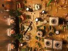
 

Attachments

  • Tp Bias Points.jpg
    Tp Bias Points.jpg
    2.5 MB · Views: 10
Last edited:
Well, you're learning several lessons at once, might be a bit overwhelming.

One of the bigger lessons is - to test your work before you really turn on the power.

Well, in a sense. You have to double check work as you are doing this - in steps. That way, if one step is wrong - the rest of the picture of the paint by numbers kit, is still operational

1649121240649.png

On a lighter, yet as serious note.

I see the work, and if you have pulled the jumper tabs or wires, and it looks like you did, but still have a AM Regulator getting hot, it means other issues UPSTREAM (before the test points) is happening - and you have to find them and fix them before you can even finish this project.

See that Electrolytic cap? The one right next to TP9? Check and make sure these soldered parts are truly soldered - and using correctly rated and values with it too. You can't use a 10V part in a 12~13.8V system - they'll fail. So let's keep this simpler and you may need to undo some of your work to correct it.

So, you have a DVM, - and you know where the AM Regulator is, pull that Regulator and double check the 3 legs of where that part goes.

Any dead shorts - then you have to find the parts it connects to and figure out WHY the short is showing up.

May mean you have to pull more parts or unsolder some more of your work - then resolder it together carefully and maybe with a new part or two you checked out of circuit that seems questionable. As you take these parts out - check the trace back at the Regulator - across to ground - to see if a short still exists - if it doesn't, you may have found the reason.

.
 
Well, you're learning several lessons at once, might be a bit overwhelming.

One of the bigger lessons is - to test your work before you really turn on the power.

Well, in a sense. You have to double check work as you are doing this - in steps. That way, if one step is wrong - the rest of the picture of the paint by numbers kit, is still operational


On a lighter, yet as serious note.

I see the work, and if you have pulled the jumper tabs or wires, and it looks like you did, but still have a AM Regulator getting hot, it means other issues UPSTREAM (before the test points) is happening - and you have to find them and fix them before you can even finish this project.

See that Electrolytic cap? The one right next to TP9? Check and make sure these soldered parts are truly soldered - and using correctly rated and values with it too. You can't use a 10V part in a 12~13.8V system - they'll fail. So let's keep this simpler and you may need to undo some of your work to correct it.

So, you have a DVM, - and you know where the AM Regulator is, pull that Regulator and double check the 3 legs of where that part goes.

Any dead shorts - then you have to find the parts it connects to and figure out WHY the short is showing up.

May mean you have to pull more parts or unsolder some more of your work - then resolder it together carefully and maybe with a new part or two you checked out of circuit that seems questionable. As you take these parts out - check the trace back at the Regulator - across to ground - to see if a short still exists - if it doesn't, you may have found the reason.

.
Well I found out why my last final wasn't working. While is was unhooking the driver and finals I melted the solder and inadvertently pushed a jumper thru the board. It works now. I'll fine tooth comb it tomorrow and see if I did any other damage.
 
I'm still hunting for a short and why I don't have modulation. I'll start again this weekend..
I checked a little last night......Basically got the radio back to where it was. I have modulation on high power with a slight hum. No modulation on low. There are a lot of bad solder joints on this radio. Even if you reflow, the connection is not guaranteed. I've been chasing after myself from soldering issues. I normally solder well but for this radio that's out the door. The problem is near the AM regulator somewhere. That I know. I was unable to adjust AM power on VR13 till I re-worked the components around the AM regulator, then the modulation was restored on high power. The regulator takes a while to get hot after several extended keys but still gets hot, so there has to be something shorting, causing a draw and also killing modulation on low power. Power and biasing are able to be adjusted but, I'm not trying to crank up the power until the other issues are corrected.
 
Last edited:
I'm still hunting for a short and why I don't have modulation. I'll start again this weekend..
I checked a little last night......Basically got the radio back to where it was. I have modulation on high power with a slight hum. No modulation on low. There are a lot of bad solder joints on this radio. Even if you reflow, the connection is not guaranteed. I've been chasing after myself from soldering issues. I normally solder well but for this radio that's out the door. The problem is near the AM regulator somewhere. That I know. I was unable to adjust AM power on VR13 till I re-worked the components around the AM regulator, then the modulation was restored on high power. The regulator takes a while to get hot after several extended keys but still gets hot, so there has to be something shorting, causing a draw and also killing modulation on low power. Power and biasing are able to be adjusted but, I'm not trying to crank up the power until the other issues are corrected.
I got modulation on lo power now and high power. I'm getting 10 watts RMS. I'll check power tomorrow with another meter and check the power draw one more time. Regulator still gets kinda hot. I'm not sure if it's too hot or not. I'll check voltages as well. Bad solder joints!
 
Check back on your pics of the RF section. There seems to be a burnt resistor just below J30. There are 2 resistors just below J30, it's the 2nd resistor below the J30 jumper.

Looks burnt in the pic.

Also, I just recently had the same issue you were have with no mod on lo power but good mod on hi power.

Turned out to be the AF Regulator standing freely in front of the passthrough regulator (AM Regulator). May want to check TR49 also.

I did notice your last final in the chain has the bias adjustment turned wide open. Kinda odd, they should never go above the 9 o'clock or above the 3 o'clock position.

Most 3400s I run across, the bias adjustments always end up being:
Driver - set at 7 o'clock position
1st final - set at 5 o'clock position
2nd final - set at 7 o'clock position

Not always the same on all connexs, but close to the above.

Andy might chime in on this, I'm still learning myself.
 
dang straight its invaluable. i read this entire thread and i never knew i could learn so much from one thread. truly excellent detailed information from handy andy the guy is brilliant with this stuff!
Actually it helps other members here if it is posted in the public forum.
This is invaluable information for future users.

73
Jeff
 
  • Like
Reactions: Hawkeye351
Well, you're learning several lessons at once, might be a bit overwhelming.

One of the bigger lessons is - to test your work before you really turn on the power.

Well, in a sense. You have to double check work as you are doing this - in steps. That way, if one step is wrong - the rest of the picture of the paint by numbers kit, is still operational


On a lighter, yet as serious note.

I see the work, and if you have pulled the jumper tabs or wires, and it looks like you did, but still have a AM Regulator getting hot, it means other issues UPSTREAM (before the test points) is happening - and you have to find them and fix them before you can even finish this project.

See that Electrolytic cap? The one right next to TP9? Check and make sure these soldered parts are truly soldered - and using correctly rated and values with it too. You can't use a 10V part in a 12~13.8V system - they'll fail. So let's keep this simpler and you may need to undo some of your work to correct it.

So, you have a DVM, - and you know where the AM Regulator is, pull that Regulator and double check the 3 legs of where that part goes.

Any dead shorts - then you have to find the parts it connects to and figure out WHY the short is showing up.

May mean you have to pull more parts or unsolder some more of your work - then resolder it together carefully and maybe with a new part or two you checked out of circuit that seems questionable. As you take these parts out - check the trace back at the Regulator - across to ground - to see if a short still exists - if it doesn't, you may have found the reason.

.
Hey I have a question man,same board but a general lee. This is the same setup....the 15c with dual 520s. Is there a reason why those diodes from source to gate aren't present in these radios that you know of ?
 
Can you post a photo?

You Need to document this one!
I sure can my friend. I've read so many of your long writeups on this forum I already knew exactly who to ask lol. Actually come to think of it I'll have to see if I have the original picture I took because it's already smoked a set of finals which I now suspect had something to do with the lack of those diodes. It was serviced by cbradiospronto and came just like that from them
 
Hmmm...Well, I just wanted to notify the site, that this might set off a chain of events - that could get interesting...

In the years I've worked with MOSFET - unless there are "EKL" and their counterparts used, the issue of self-biased MOSFET is a rare realm of effort.

Bipolar can do it thru their "PN junction presence" at the Base to connect itself to the other two in the substrate, Collector and Emitter. RF gets rectified there - but remember too, the CLASS the thing works in, Class C and Class D for it's biasing and power - the reason why it works the way it does is by the Collector - using the BASE to flow both to the Emitter.

It's when you ADD in a method to turn the transistor on using a smaller level of signal - using BIAS - does the post you made - worth letting others know of the approach - else we just might not be seeing a step they did - and we missed it because they did this further up a chain or feeder in the TX line.

A diode of some sort, or a biasing method - was used in/and still is used, just getting the MOSFET to turn on in the presence of RF. Now, I'm - not saying it's impossible, just a lot of energy is needed in the RF signal to make the GATE turn on - rendering much of the signal that can be used, lost to the effort of just getting the thing turned on - there is not much left to reproduce.

So double check to see if they "regulated" the Bias using a feeder from - say, the 8V+ rail or TX line - so they could bias the Gate with just enough to turn it on when it was in TX mode.
 
Per HandyAndy :"When you set BIAS - you set in mA Setting (Amperage) and check Source (Emitter - Ground) - Drain (Collector is Center Leg on Bipolar - HOT from AM Regulator) (from Gate idle) mA draw - through our Test Point to AM Regulator."

I need clarification on this statement please, as I read it as checking current draw, mosfet unsoldered, from drain pad thru source pad. However, it says through our test point (TP7/8) to AM reg (TP9). Which locale is this measurement taken? I have always used the TPs for this, and I think I am reading this statement wrong. I find this useful but hard to follow, so I am rewriting this thread to make the process more straightforward and gain more understanding. I will have more questions later. Thanks.
 
I think my big issue is driver bias adjustment on this chassis. IF this radio has ssb it wouldn't be an issue, but as it is am/fm only, there is always a carrier present so the 55ma driver figure leaves me with a zero deadkey such as expected with ssb. I suppose a driver mA spec for say a 4 watt am dk would be good to know. I may pull my 959 out and get a reading from it in am to extrapolate the expected draw. I got really hung up on this stripped down export and my usual procedure for such.
 

dxChat
Help Users
  • No one is chatting at the moment.