Warning! This is a ROUGH DRAFT and not yet quite complete.
It's listed as "Mark 4A", since it's incredibly rare to find a Mark 4 transmitter that actually works.
With any luck, corrections and revisions to this procedure will follow before I ship a D-I-Y version.
Dang! Only took 29 pictures to get this thing hooked up in the radio. I'll finish with the setup procedure soon.
When I posted the Mark 3 version, it turned out to be too long. The forum wouldn't let me post it, so this one is split into two posts.
73
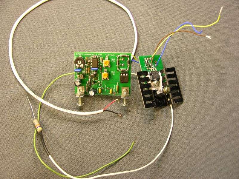
Installing the Nomad Radio carrier control in the Browning Mark 4A transmitter.
Preliminary 6/18/15
The very first thing that has to happen is removing the top and bottom covers of the transmitter. Removing the bottom cover usually changes the peak setting of the plate-tune control on the rear of the chassis. Connect the mike, dummy load and wattmeter to the transmitter, turn it on and let it warm up. Now check to see that the bias is set correctly. Next select AM mode, key the mike and set the plate tune to its peak setting. This is the starting point before making any modifications. If the transmitter is not performing properly in its stock condition, STOP RIGHT NOW AND DON'T PROCEED ANY FURTHER until it has been repaired. If you install this accessory on a transmitter that is partly crippled or weak, your final result will suffer. And I won't be the tiniest bit sympathetic.
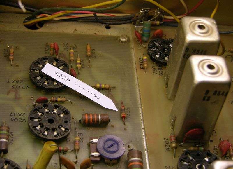
Above all you should check to see that the 3.3k 1/2-Watt resistor R229 is not burned. It's on the audio board, at the edge adjacent to the RF board. IF THIS PART IS DARKENED, YOU HAVE A PROBLEM WITH THE MODE SELECTOR. DON'T PROCEED ANY FURTHER UNTIL THIS PROBLEM HAS BEEN ADDRESSED. No, we won't cover the means to fix this failure. But it's a very common problem. The brown bakelite insulation on the mode selector switch just breaks down over the decades and causes fault currents between the separate circuits on that switch. WHEN R229 BLOWS OUT YOU WON'T HAVE ANY MIKE AUDIO ANYWAY. Simply installing a fresh resistor WON'T fix the problem. The burned resistor is a result of trouble with the mode selector. The burned resistor is just a symptom, not the actual problem.
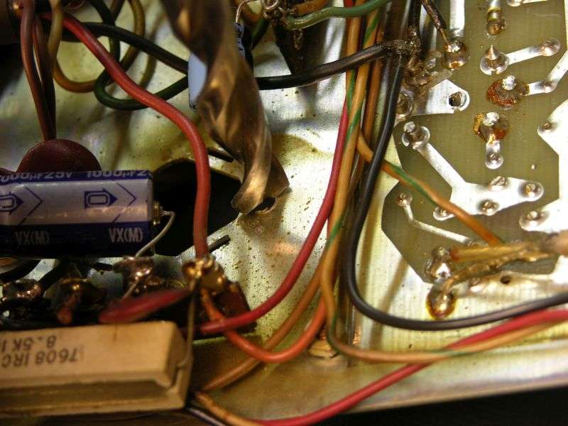
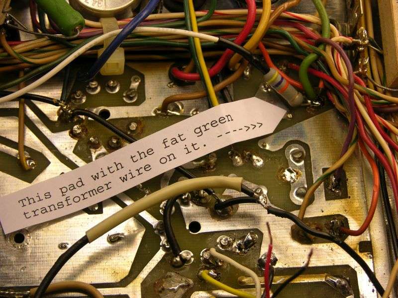
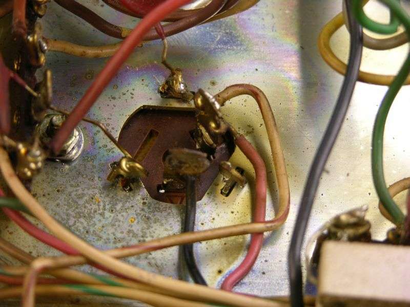
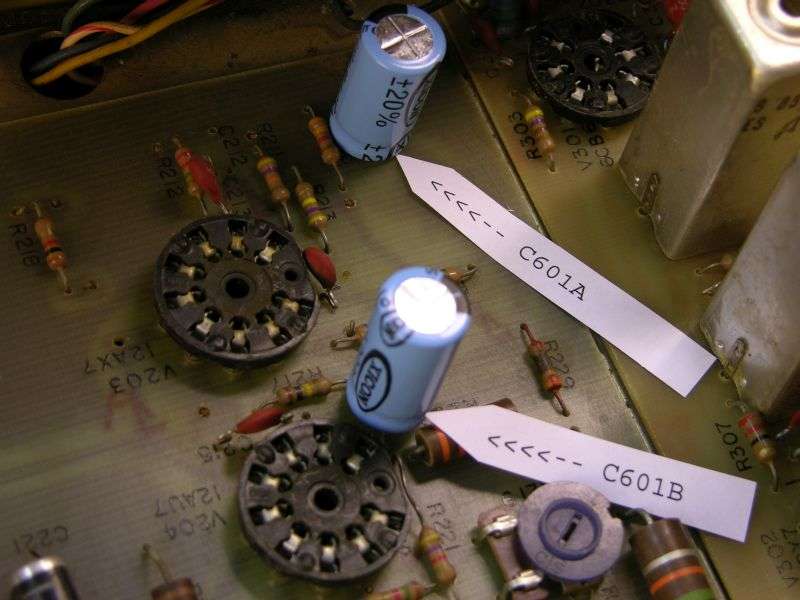
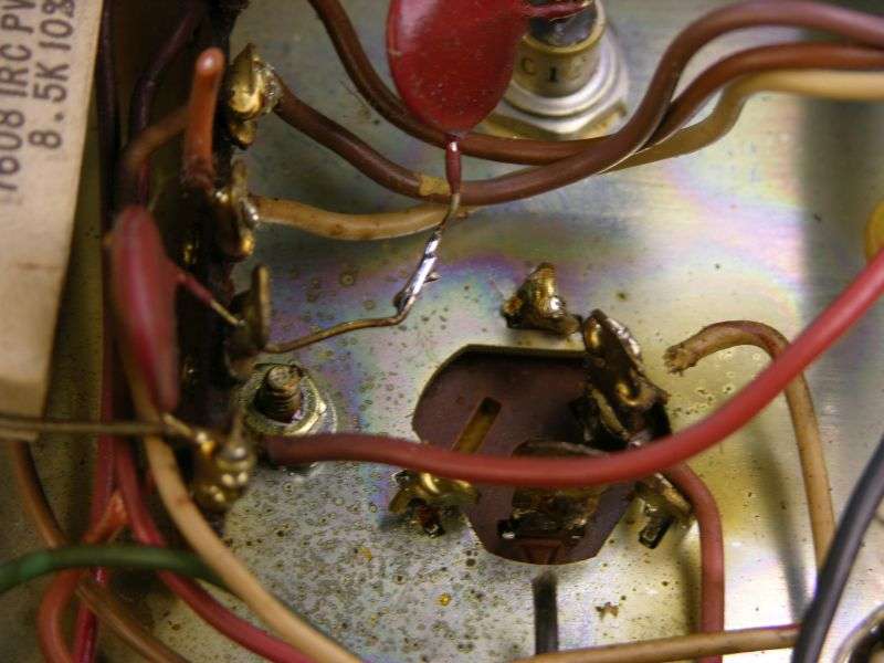
The first step is to remove the two-section twist-lock 'can' electrolytic capacitor C601. It's at the rear just to the front from the 10-Watt zener diode, next to the modulation transformer.
If the factory-original part is still there, it needs to be replaced due to age alone. And if a new replacement is there, we need to remove it anyway to make room for the control transistor to be installed there.
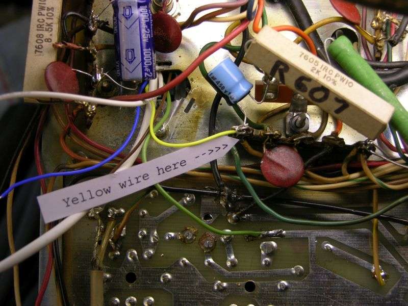
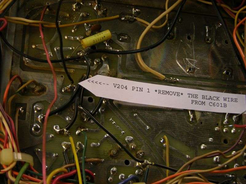
The single black wire on one lug of C601 gets removed. Follow this wire to the audio pc board, where it's soldered to the pad for pin 1 of V204. Remove the black wire from this hole in the pc board. On the component side of the audio board insert the positive lead of one 10uf 450V radial cap in this hole. The negative lead of the new cap goes into a hole just next to it in the ground foil. Solder both leads.
The other lug of C601 has two wires, a pink wire and a white wire with a brown stripe. Cut both of these at C601. Follow the pink wire to a foil pad on the audio board at the front-outboard corner. The white/brown wire goes to the mode selector. Thread the free end of the white/brown wire along the front panel to reach the corner of the audio board where the pink wire is attached.
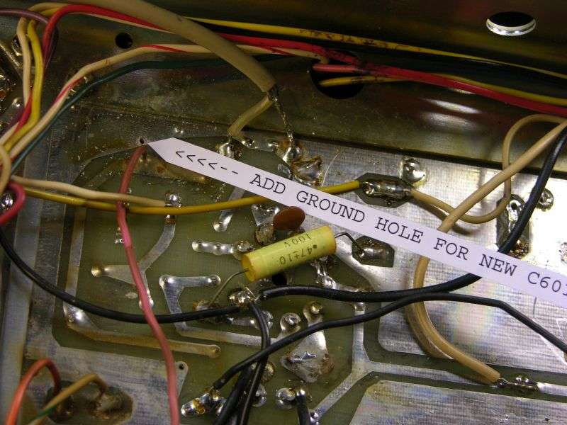
Now drill a hole in the ground foil alongside the foil pad with the pink wire on it. Remove the pink wire. Insert the other 10uf 450 Volt radial cap on the component side with the positive lead into the hole where the pink wire had been, the negative lead into the new hole you drilled in the ground foil. Strip the end of the white/brown wire. It will fit into the hole in the foil pad alongside the positive lead of the 10uf cap. Now solder both leads on the new 10uf cap, along with the white/brown wire.
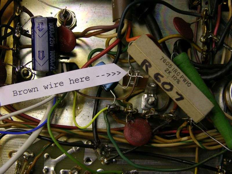
There are two bare wires soldered to ground lugs on C601. One of them goes to the ground lug on the adjacent tie strip. The other one is the ground lead of a disc capacitor. Clip both of them as close to the lug as possible. Lap these two leads alongside each other and solder. Now would be a good time to use a needle-nose plier to twist the ground lugs from C601 until they snap and remove C601 completely from the chassis.
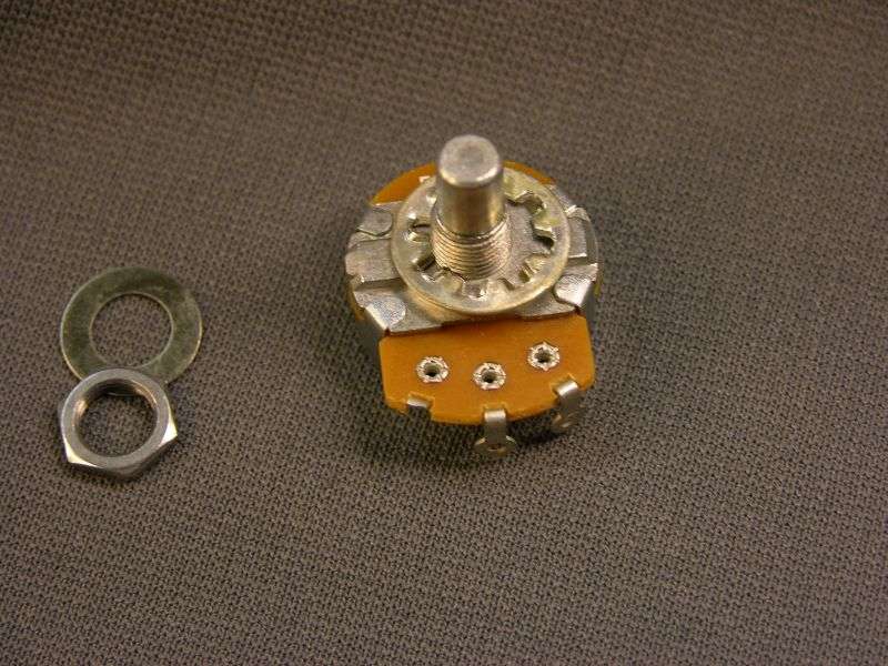
The next thing you need to do is install a mike-gain control on the front panel. The 'Test Reset/LED' knob is an obvious choice. The control we supply with the installation kit has three wires on it, a white wire on the clockwise lug, yellow on the wiper lug and a black wire on the counterclockwise lug.
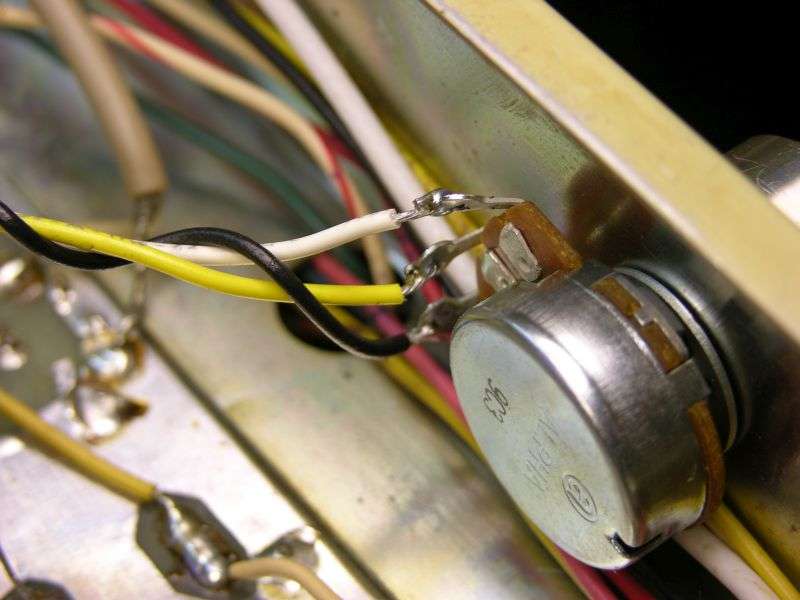
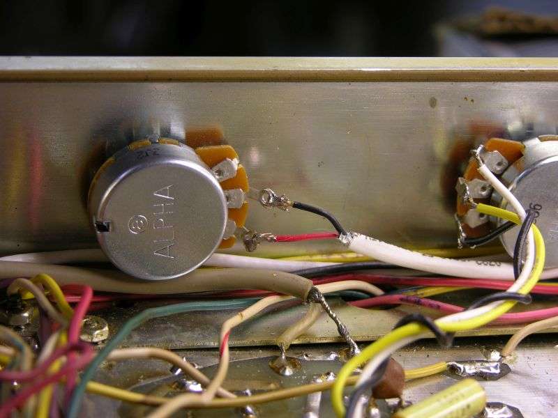
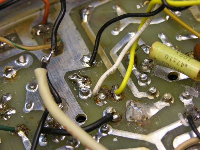
There are two black wires on the solder side of the audio board connected to the blue mike-gain trimpot R219. One of these black wires is soldered to V204, the 12AU7 pin 2. The other one is soldered to a foil pad immediately towards the front from this pad. Remove these two black wires completely. The white wire (clockwise lug of the new control) goes to the pin 2 pad on V204. The yellow wire is the wiper (center) lug of the new mike gain control. The yellow wire goes to the pad immediately to the front from the pin 2 pad where the white wire was just soldered. The black wire from the counterclockwise lug of the new mike-gain control gets lap-soldered to the ground foil as shown.
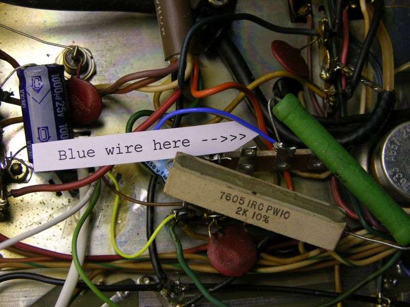
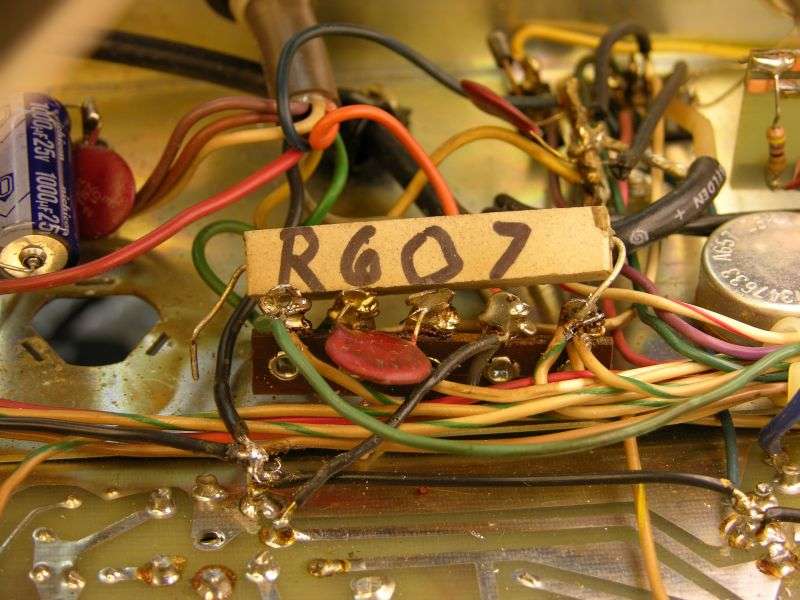
Next task is to unsolder the OUTBOARD end of R607. Suck the solder from the lug so that wires can be inserted into it later. Suck the solder from the lug at the other end of R607. We'll need to insert another resistor lead there, as well.
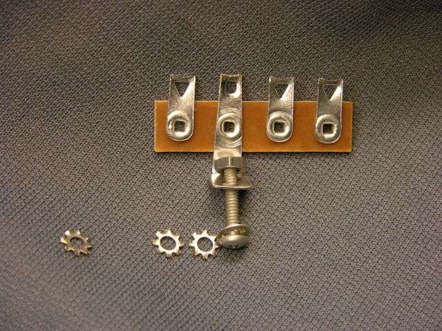
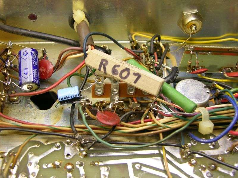
Next step is to remove the 4-40 screw and nut that hold down this tie strip. This screw also holds down the front end of the audio choke L601.
There are four wires on the rear side of this tie strip. Bend them down towards the chassis deck so they can pass under a new tie strip that gets mounted on the same screw that holds down this one.
On some radios, you'll find that this screw has Loc-Tite on it, and the screw will snap when you try to loosen it. Not to worry, we pack a new 4-40 screw and nut with the new tie strip. The new tie strip is bolted alongside and to the rear of the radio from the original one.
The outboard lead of R607 that we unhooked is probably too short to reach the outboard lug of the new tie strip. That's why we provide a new 2k 10-Watt resistor with the kit. If the leads on R607 are too short, remove the old one now.
The green 15k 7 Watt resistor now gets one lead into the inboard-most lug of the old tie strip. The other lug goes into the lug of the new tie strip as shown. Don't solder either end yet.
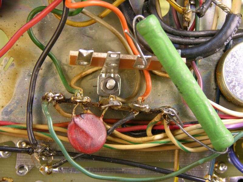
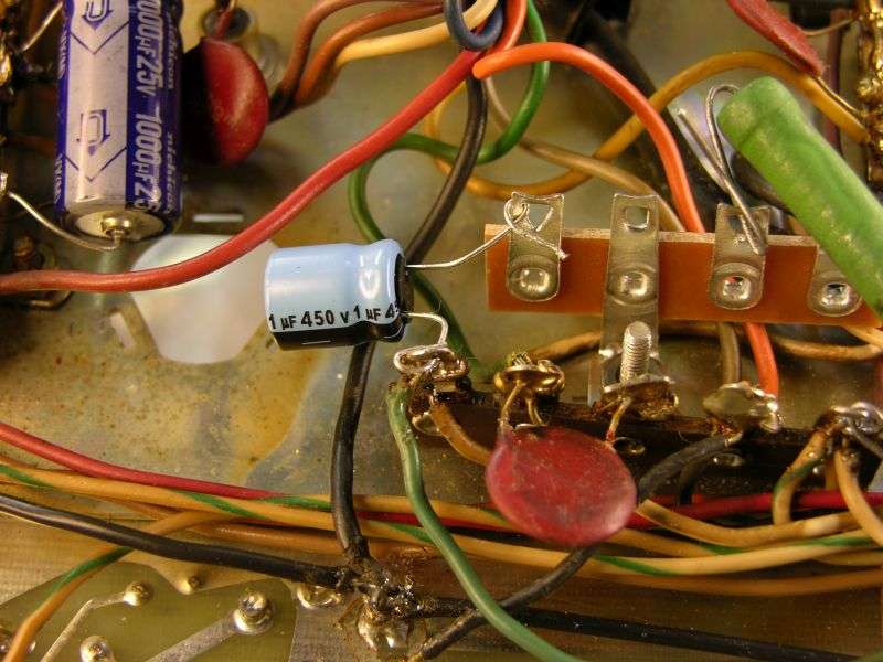
Find the 1uf 450V radial cap from the supplied parts. Mount it with the negative lead to the front tie strip, in the outboard-end lug where R607 was removed. The positive lead of the 1uf cap goes to the outboard-end lug of the new tie strip.
Now install R607, either the old one if the leads are long enough, or the new one. The original resistor may have been marked 2.7k, 2.5 or 2.4k. The 2k resistor will provide a little more peak power than the higher resistance values. Feel free to experiment. A lower resistance value gets you a higher peak output. Just don't use any value less than 1.5k. We have found this to be the upper limit in practice. Any less than 1.5k may make the wattmeter happier, but you will sacrifice the audio level you can get.
You can solder the inboard lug of the old tie strip, where the green 15k and R607 are inserted. DO NOT solder the other three lugs yet.
---End of part one of two ---
It's listed as "Mark 4A", since it's incredibly rare to find a Mark 4 transmitter that actually works.
With any luck, corrections and revisions to this procedure will follow before I ship a D-I-Y version.
Dang! Only took 29 pictures to get this thing hooked up in the radio. I'll finish with the setup procedure soon.
When I posted the Mark 3 version, it turned out to be too long. The forum wouldn't let me post it, so this one is split into two posts.
73
Installing the Nomad Radio carrier control in the Browning Mark 4A transmitter.
Preliminary 6/18/15
The very first thing that has to happen is removing the top and bottom covers of the transmitter. Removing the bottom cover usually changes the peak setting of the plate-tune control on the rear of the chassis. Connect the mike, dummy load and wattmeter to the transmitter, turn it on and let it warm up. Now check to see that the bias is set correctly. Next select AM mode, key the mike and set the plate tune to its peak setting. This is the starting point before making any modifications. If the transmitter is not performing properly in its stock condition, STOP RIGHT NOW AND DON'T PROCEED ANY FURTHER until it has been repaired. If you install this accessory on a transmitter that is partly crippled or weak, your final result will suffer. And I won't be the tiniest bit sympathetic.
Above all you should check to see that the 3.3k 1/2-Watt resistor R229 is not burned. It's on the audio board, at the edge adjacent to the RF board. IF THIS PART IS DARKENED, YOU HAVE A PROBLEM WITH THE MODE SELECTOR. DON'T PROCEED ANY FURTHER UNTIL THIS PROBLEM HAS BEEN ADDRESSED. No, we won't cover the means to fix this failure. But it's a very common problem. The brown bakelite insulation on the mode selector switch just breaks down over the decades and causes fault currents between the separate circuits on that switch. WHEN R229 BLOWS OUT YOU WON'T HAVE ANY MIKE AUDIO ANYWAY. Simply installing a fresh resistor WON'T fix the problem. The burned resistor is a result of trouble with the mode selector. The burned resistor is just a symptom, not the actual problem.
The first step is to remove the two-section twist-lock 'can' electrolytic capacitor C601. It's at the rear just to the front from the 10-Watt zener diode, next to the modulation transformer.
If the factory-original part is still there, it needs to be replaced due to age alone. And if a new replacement is there, we need to remove it anyway to make room for the control transistor to be installed there.
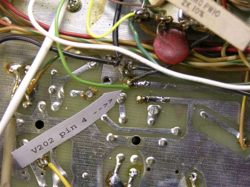
The single black wire on one lug of C601 gets removed. Follow this wire to the audio pc board, where it's soldered to the pad for pin 1 of V204. Remove the black wire from this hole in the pc board. On the component side of the audio board insert the positive lead of one 10uf 450V radial cap in this hole. The negative lead of the new cap goes into a hole just next to it in the ground foil. Solder both leads.
The other lug of C601 has two wires, a pink wire and a white wire with a brown stripe. Cut both of these at C601. Follow the pink wire to a foil pad on the audio board at the front-outboard corner. The white/brown wire goes to the mode selector. Thread the free end of the white/brown wire along the front panel to reach the corner of the audio board where the pink wire is attached.
Now drill a hole in the ground foil alongside the foil pad with the pink wire on it. Remove the pink wire. Insert the other 10uf 450 Volt radial cap on the component side with the positive lead into the hole where the pink wire had been, the negative lead into the new hole you drilled in the ground foil. Strip the end of the white/brown wire. It will fit into the hole in the foil pad alongside the positive lead of the 10uf cap. Now solder both leads on the new 10uf cap, along with the white/brown wire.
There are two bare wires soldered to ground lugs on C601. One of them goes to the ground lug on the adjacent tie strip. The other one is the ground lead of a disc capacitor. Clip both of them as close to the lug as possible. Lap these two leads alongside each other and solder. Now would be a good time to use a needle-nose plier to twist the ground lugs from C601 until they snap and remove C601 completely from the chassis.
The next thing you need to do is install a mike-gain control on the front panel. The 'Test Reset/LED' knob is an obvious choice. The control we supply with the installation kit has three wires on it, a white wire on the clockwise lug, yellow on the wiper lug and a black wire on the counterclockwise lug.
There are two black wires on the solder side of the audio board connected to the blue mike-gain trimpot R219. One of these black wires is soldered to V204, the 12AU7 pin 2. The other one is soldered to a foil pad immediately towards the front from this pad. Remove these two black wires completely. The white wire (clockwise lug of the new control) goes to the pin 2 pad on V204. The yellow wire is the wiper (center) lug of the new mike gain control. The yellow wire goes to the pad immediately to the front from the pin 2 pad where the white wire was just soldered. The black wire from the counterclockwise lug of the new mike-gain control gets lap-soldered to the ground foil as shown.
Next task is to unsolder the OUTBOARD end of R607. Suck the solder from the lug so that wires can be inserted into it later. Suck the solder from the lug at the other end of R607. We'll need to insert another resistor lead there, as well.
Next step is to remove the 4-40 screw and nut that hold down this tie strip. This screw also holds down the front end of the audio choke L601.
There are four wires on the rear side of this tie strip. Bend them down towards the chassis deck so they can pass under a new tie strip that gets mounted on the same screw that holds down this one.
On some radios, you'll find that this screw has Loc-Tite on it, and the screw will snap when you try to loosen it. Not to worry, we pack a new 4-40 screw and nut with the new tie strip. The new tie strip is bolted alongside and to the rear of the radio from the original one.
The outboard lead of R607 that we unhooked is probably too short to reach the outboard lug of the new tie strip. That's why we provide a new 2k 10-Watt resistor with the kit. If the leads on R607 are too short, remove the old one now.
The green 15k 7 Watt resistor now gets one lead into the inboard-most lug of the old tie strip. The other lug goes into the lug of the new tie strip as shown. Don't solder either end yet.
Find the 1uf 450V radial cap from the supplied parts. Mount it with the negative lead to the front tie strip, in the outboard-end lug where R607 was removed. The positive lead of the 1uf cap goes to the outboard-end lug of the new tie strip.
Now install R607, either the old one if the leads are long enough, or the new one. The original resistor may have been marked 2.7k, 2.5 or 2.4k. The 2k resistor will provide a little more peak power than the higher resistance values. Feel free to experiment. A lower resistance value gets you a higher peak output. Just don't use any value less than 1.5k. We have found this to be the upper limit in practice. Any less than 1.5k may make the wattmeter happier, but you will sacrifice the audio level you can get.
You can solder the inboard lug of the old tie strip, where the green 15k and R607 are inserted. DO NOT solder the other three lugs yet.
---End of part one of two ---