
You are using an out of date browser. It may not display this or other websites correctly.
You should upgrade or use an alternative browser.
You should upgrade or use an alternative browser.
-
You can now help support WorldwideDX when you shop on Amazon at no additional cost to you! Simply follow this Shop on Amazon link first and a portion of any purchase is sent to WorldwideDX to help with site costs.
-
A Winner has been chosen for the 2026 July 4th Retevis RA89R Giveaway! Click Here to see who won!
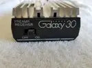
Galaxy 30 reciever preamp
- Thread starter Copycat32
- Start date

I have one. It uses a MS1307 transistor. Mine gave up so I opened it up yesterday and replaced the transistor but I think one of the diodes got hurt. I need a schematic also. 73's
Would be interesting to see inside of the Galaxy amp.I have one. It uses a MS1307 transistor. Mine gave up so I opened it up yesterday and replaced the transistor but I think one of the diodes got hurt. I need a schematic also. 73's
At any rate, wonder if the CTE Mosquito schematic is similar. Probably not the same, but should be a fairly simple circuit in either of them.
I took a couple pictures but it wasn't for showing the whole board. Not much to it. Mine had a burned circuit trace off of the base of the transistor but fixing that and the new 1307 didn't fix it. Thanks for your schematic!
Marty
Marty
Attachments
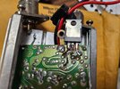
If you wanted to add pictures of the whole board, maybe we can piece together the schematic. It would take a few angles to get all the cap values.I took a couple pictures but it wasn't for showing the whole board. Not much to it. Mine had a burned circuit trace off of the base of the transistor but fixing that and the new 1307 didn't fix it. Thanks for your schematic!
Marty
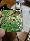
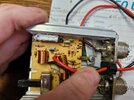
The collector looks like the solder is on the trace mask and not making good contact. It also looks like the collector is really close to touching the emitter.
Oh it is close but is separated. The DMM tested that, as I was questioning it also. I just got it back together, tomorrow maybe I can pull it back apart and get the group a few good pictures. It powers on but doesn't transmit. It does Recieve in the on position tho. It pulls about 1 volt when hooked up. I didn't check amperage, sorry. I kinda hurried thru it.
I'm retired, I don't mind (if I don't FORGET).
Don't get old.....
Marty (Pops)
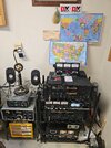
Here is my Radio Staion, if you'd like to see a video. I run a Maco M103C that is 59' to the tip, vertically.
I'm retired, I don't mind (if I don't FORGET).
Don't get old.....
Marty (Pops)
Here is my Radio Staion, if you'd like to see a video. I run a Maco M103C that is 59' to the tip, vertically.
Attachments
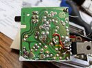
There is no relay visible in the pics. The Mosquito schemo above shows small signal diodes taking the place of the relay. Looks as if this one is built that way.
Just one problem. You must have the power connected before you transmit barefoot through it. The diodes need DC power to provide the receive or barefoot side. And if you transmit through it with no DC power applied, this tends to blow out the diodes. Good chance that's an issue with your jewel.
73
Just one problem. You must have the power connected before you transmit barefoot through it. The diodes need DC power to provide the receive or barefoot side. And if you transmit through it with no DC power applied, this tends to blow out the diodes. Good chance that's an issue with your jewel.
73
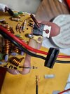
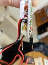
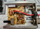
Well I took it apart just for pictures. When I power it "on", it pulls about 1 volt from my power supply but I haven't tried it with a radio. I would venture to say at least one diode is probably smoked. The circuit traces are SUPER thin and easy to hurt.
Attachments
-
 20250528_105835.jpg1.5 MB · Views: 265
 -
 20250528_105633.jpg1.6 MB · Views: 263
 -
 20250528_104553.jpg1.8 MB · Views: 271
 -
 20250528_104506.jpg1.6 MB · Views: 262
 -
 20250528_104450.jpg1.6 MB · Views: 267
 -
 20250528_104127.jpg1.2 MB · Views: 252
 -
 20250528_104054.jpg1.9 MB · Views: 267
 -
 20250528_104029.jpg1.9 MB · Views: 272
I will try to figure out the schematic when i get to work. It should be a slow day.
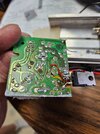
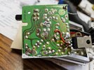
I had to flip the image to match the trace side. I couldn't see the component values, but that is not important. Looks like with the switch on, receive passes through C3 because the RX signal is too weak to forward bias any of the diodes.
Transmit is the interesting part, and with those diodes, I am reminded of two youtube videos, one from Applied Science (his NMR video), and W2AEW's video (#200), both talking about lambda/4 networks that block only strong signals (but I don't know the cap values so I cannot confirm if that's what is going on here).
D1-D6 appear to be 4148's, but I think D7 is a zener.
As for troubleshooting, we could start poking around to see what's going on if you are up to it. I don't know the current rating of your supply but dropping a whole volt while it's just idling is not good.
If you want to pay the shipping, I could fix the collector trace and put the transistor back in its holes, and maybe even figure out the issue, but keep in mind that USPS and UPS have been having serious package theft issues lately, and since it's not worth the insurance, mailing it is a gamble.


edit, forgot to label the inductor above D4, that one is L2
edit2, a few captain cokes and a doobie later and I don't see any of that neat lambda/4 stuff is happening, idk. maybe ill see it again tomorrow lol
Transmit is the interesting part, and with those diodes, I am reminded of two youtube videos, one from Applied Science (his NMR video), and W2AEW's video (#200), both talking about lambda/4 networks that block only strong signals (but I don't know the cap values so I cannot confirm if that's what is going on here).
D1-D6 appear to be 4148's, but I think D7 is a zener.
As for troubleshooting, we could start poking around to see what's going on if you are up to it. I don't know the current rating of your supply but dropping a whole volt while it's just idling is not good.
If you want to pay the shipping, I could fix the collector trace and put the transistor back in its holes, and maybe even figure out the issue, but keep in mind that USPS and UPS have been having serious package theft issues lately, and since it's not worth the insurance, mailing it is a gamble.
edit, forgot to label the inductor above D4, that one is L2
edit2, a few captain cokes and a doobie later and I don't see any of that neat lambda/4 stuff is happening, idk. maybe ill see it again tomorrow lol
Last edited:
At this point, I'm 5 drinks in, but I think D5, C4 and D7 clip the positive peaks to the zener voltage D7. C4 holds it so it doesn't take from the signal each cycle and D5 prevents that cap from draining back on negative swings.
The resistors appear to put about 420uA across R1 and R2. With about 82% of that going into the base (ballparkin' that $#!<), and a gain of 70 to 140, you get a collector current between 24 and 48mA of bias current (assuming 12v). Looks normal.
D6 and R4 attenuate negative peaks so they don't destroy the b-e junction (whats that take again? -5v?).
C2 prevents DC from turning on D1 or D2, and the weak RX signals are not strong enough to forward bias them nor can they drive the amplifier via R2, so RX goes to the radio only. Strong signals from the radio forward bias D1 and D2 and go to the base of the transistor.
D4 and D5 conduct during strong signals and do not conduct during RX, so it could be assumed L2 and C3 form a series resonant circuit at 27MHz during RX and L2 is to ground during TX to form an L match with C9.
Pretty sure C5-L4-C7 are a pi filter, and L3-C6 form an L match to match the transistor to the filter.
All this could be confirmed with the values of the caps and some coil measurements, but thats my best guess for now.
If I stay up any later, I'll probably start saying stupid stuff, so I'm otta here. Have a good morning! And although unrelated, go check out those lambda/4 videos anyhow, you'll be glad you did")
The resistors appear to put about 420uA across R1 and R2. With about 82% of that going into the base (ballparkin' that $#!<), and a gain of 70 to 140, you get a collector current between 24 and 48mA of bias current (assuming 12v). Looks normal.
D6 and R4 attenuate negative peaks so they don't destroy the b-e junction (whats that take again? -5v?).
C2 prevents DC from turning on D1 or D2, and the weak RX signals are not strong enough to forward bias them nor can they drive the amplifier via R2, so RX goes to the radio only. Strong signals from the radio forward bias D1 and D2 and go to the base of the transistor.
D4 and D5 conduct during strong signals and do not conduct during RX, so it could be assumed L2 and C3 form a series resonant circuit at 27MHz during RX and L2 is to ground during TX to form an L match with C9.
Pretty sure C5-L4-C7 are a pi filter, and L3-C6 form an L match to match the transistor to the filter.
All this could be confirmed with the values of the caps and some coil measurements, but thats my best guess for now.
If I stay up any later, I'll probably start saying stupid stuff, so I'm otta here. Have a good morning! And although unrelated, go check out those lambda/4 videos anyhow, you'll be glad you did
Last edited:
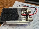
Wow, you amaze me Brandon. Thanks for straining the brain on this thing. That transistor is supposed to sit like it does, as it uses a metal strap to hold it against the heatsink. I may open it up again if I get more curious. My little 4 amp power supply is all I was using, not my 25 amp unit (I have two that I run in parallel for 50 amps). I was just surprised that any draw at all showed on a voltmeter that is hooked across my + & - terminals. I never checked amp draw.
I really appreciate your "legwork" and wish I were there with you to share your thought process (and the cocktails and a smoke). Maybe this thing will work again if I put some time into it.
Thanks again, I am so surprised at the breakdown you did.
73's
Marty
On a side note, I worked for USPS for 35 years (25 as Postmaster), and just retired last year, as I saw the problems coming, so I jumped ship! I also AGREE with you on package theft. I had a set of car door side mouldings, correct color and unobtainable, come up missing. It was all packed in a fishing rod TUBE but yet both ends were cut open and I received an empty tube for $200. I don't use them to ship anything anymore.
Last edited:
Would be interesting to see inside of the Galaxy amp.
At any rate, wonder if the CTE Mosquito schematic is similar. Probably not the same, but should be a fairly simple circuit in either of them.
View attachment 73026
Attachments
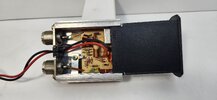
So they were not ferrite beads on the leads of the big resistor, just insulation. Thanks for the picture, I'll have to update my schematic. I still wonder whats under the glue between the power lead and the RFC though.
dxChat
- No one is chatting at the moment.