I am trying to repair a galaxy dx2517 with the newer mosfet board. I originally start troubleshooting it because it was outputting almost no power and could not properly adjust bias voltage or current either way I tried. and at some point along the way, it started to switch into tx on its own even in rx after being powered on for about 20 seconds. I'd let it cool off and turn it back on and it did this consistantly after being on for 20 seconds. And now when you power on the radio it immediately tries to switch into rx and tx at the same time and the rx/tx led on the front looks like the red and green light are on together. I've been going through checking parts in the rf driver and final sections, the regulator section near the q37 regulator, and in the tx,rx switching circuit around the q30 through q33 switching transistors and have not found a problem yet. after checking most of the components in these areas I have yet to find a shorted part or problem. I've started replacing a few electrolytics, regulator transistors, a few diodes. I've reflowed some of the areas of solder and have not seen a cold solder joint. I have been careful in soldering and using another galaxy board to compare and haven't found any bridged connections. No dark burnt components. I do have a temperature gun to check for hot areas, I'm hoping someone more knowledgeable can offer some advice and point me in the right direction of where/how to trace the problem. I do not want to give up on this radio since I am learning how to troubleshoot as a hobby. I have minimal experience under my belt and hoping to fix this one to learn something from it. I am new to this forum and hoping I'm in the right place for some coaching. I'm hoping to fix the tx switching problem so I can go back to troubleshooting the bias voltage issue. I can check voltages or anything else at someone's request. The driver and finals are removed while I've been troubleshooting, hopefully that's not a problem. thanks in advance!

You are using an out of date browser. It may not display this or other websites correctly.
You should upgrade or use an alternative browser.
You should upgrade or use an alternative browser.
-
You can now help support WorldwideDX when you shop on Amazon at no additional cost to you! Simply follow this Shop on Amazon link first and a portion of any purchase is sent to WorldwideDX to help with site costs.
-
A Winner has been chosen for the 2026 July 4th Retevis RA89R Giveaway! Click Here to see who won!
Galaxy DX2517 Troubleshooting Help
- Thread starter Junkyarddog76
- Start date

What if the bias board, the driver, and both finals are already removed and it still does this? I think I’ve even tried removing q54 regulator and changing it and it does not fix it.I would unplug the bias-test jumper, sometimes called the "mirror board" and see if the radio will receive normally. If so, shorted driver/final transistors are causing the mischief.
73
I found the thread where I broke down the keying circuit on a 55v. I think it is the same. Check it out if you want to know how to troubleshoot that part of the circuit.
The first thing I would check is the KB362 diode (D71, its two diodes built into one package). I will skip the detailed explanation as it is already in the linked thread.
The first thing I would check is the KB362 diode (D71, its two diodes built into one package). I will skip the detailed explanation as it is already in the linked thread.
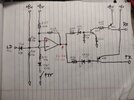
This is the keying circuit redrawn to make it easier to see whats going on.

There is a reason Cable Guy asked about the voltages on pins 5, 6 and 7. Let me explain how this circuit works.
R166 and R169 form a voltage divider to provide a reference voltage of 38.4% of the regulated supply and feeds it to the op amp for comparison.
R167, R171 and R168 also form a voltage divider that changes value depending on whether the PTT is pressed or not. R168, being at the output of the op amp (which goes high and low) is effectively switching between being in parallel with R167 and...
Attachments
That diode was famously vulnerable to getting toasted by touching ground on a loosened mike socket in mobile radios with that circuit board. Even briefly touching grounded metal would pop it. We adopted the habit of lap-soldering three 1N4148 diodes in series, to replace D71. For some reason just two of that diode would not always behave properly. Three of them always seemed to. A plastic sleeve over the series string would prevent a repeat of ground contact.
I suppose the original KB362 could be had, but with plenty of 1N4148 on hand, just couldn't justify the time and cost of stocking it. A diode test of that part should read around 1.3 10 1.4 Volts or so.
73
I suppose the original KB362 could be had, but with plenty of 1N4148 on hand, just couldn't justify the time and cost of stocking it. A diode test of that part should read around 1.3 10 1.4 Volts or so.
73
I've been studying that thread to understand the circuit better. I cant check voltages for rf and tx because it's stuck in tx or both. But the voltages on IC7 are:I found the thread where I broke down the keying circuit on a 55v. I think it is the same. Check it out if you want to know how to troubleshoot that part of the circuit.
The first thing I would check is the KB362 diode (D71, its two diodes built into one package). I will skip the detailed explanation as it is already in the linked thread.
This is the keying circuit redrawn to make it easier to see whats going on.
There is a reason Cable Guy asked about the voltages on pins 5, 6 and 7. Let me explain how this circuit works.
R166 and R169 form a voltage divider to provide a reference voltage of 38.4% of the regulated supply and feeds it to the op amp for comparison.
R167, R171 and R168 also form a voltage divider that changes value depending on whether the PTT is pressed or not. R168, being at the output of the op amp (which goes high and low) is effectively switching between being in parallel with R167 and...
Pin 1: 4.95v Pin 8: 8.95v
Pin 2: 4.95v Pin 7: fluctuates heavily from about 0.8 to 2 volts or so
Pin 3: 4.95v Pin 6: 3.6v fluctuates very slightly from 3.4 to 3.6v
Pin 4: 11mv Pin 5: fluctuates heavily from about 1.8 to 3.6 volts
A few other measurements were:
R169- 9.55v on the left lead from the top, 9.25v on the right lead from the top
R167- 0v on either lead from top
R168- 0v on either lead from the top
Here and there I'll hear a little static trying to come on and off like maybe it's trying to switch back and forth. I've been checking diodes and transistors when I can and I have not found a shorted diode or transistor yet. I also can't check certain things on your hand drawn schematic because I cannot for the life of me find q38(while I can see q37 on the heat sink and q39 on the board) and I also cannot find R166.
Can anything be determined from these measurements to help direct me in the right area? I don't understand why there is 9 volts on either side of R169 when one end is supposed to be grounded and the other end meets pin 6 of IC7 when there is 3.6 volts right on pin 6, not 9 volts like at R169.
I also noticed q35 was burning up after I replaced factory D72 with 2 series 4148's so I listened to what one of you guys said and tried adding a 3rd diode in series and it stopped getting hot. So I guess for the rest of those diodes I replace I'm going to just start using 3 in series which got me like 1.7v drop.I found the thread where I broke down the keying circuit on a 55v. I think it is the same. Check it out if you want to know how to troubleshoot that part of the circuit.
The first thing I would check is the KB362 diode (D71, its two diodes built into one package). I will skip the detailed explanation as it is already in the linked thread.
This is the keying circuit redrawn to make it easier to see whats going on.
There is a reason Cable Guy asked about the voltages on pins 5, 6 and 7. Let me explain how this circuit works.
R166 and R169 form a voltage divider to provide a reference voltage of 38.4% of the regulated supply and feeds it to the op amp for comparison.
R167, R171 and R168 also form a voltage divider that changes value depending on whether the PTT is pressed or not. R168, being at the output of the op amp (which goes high and low) is effectively switching between being in parallel with R167 and...
Before i get too far into reading this, I think I should point out that the component numbers in my schematic are for the 55v, not the 2517. For instance, R169 in a 2517 is the supply for the balanced modulator, so reading rail voltage there is expected.
I think I should re-draw the switching schematic to show the part numbers used in the 2517.
I think I should re-draw the switching schematic to show the part numbers used in the 2517.
Ohhh okay haha that would make complete sense I just assumed it was the same. If you were able to do that, that would be awesome then I could try taking a second look at it with the new schematic and maybe be less confused.Before i get too far into reading this, I think I should point out that the component numbers in my schematic are for the 55v, not the 2517. For instance, R169 in a 2517 is the supply for the balanced modulator, so reading rail voltage there is expected.
I think I should re-draw the switching schematic to show the part numbers used in the 2517.

Edit: I see I missed R170 in the 55V schematic (R184 in this one).
Last edited:
I'm accustomed to just pulling out Q30, 31 and Q33 to test each. D70 and 71 can be tested in circuit. The voltage on IC5 pin 5 has to be higher than pin 6 to make the radio receive. This should put at least 8 Volts onto pin 7. If the voltage on pin 7 is too low, Q33 will partially turn on, activating transmit circuits while the radio should be receiving.
73
73
9.25v at the balanced modulator makes me think something is wrong with the 8v regulator.

The supply (13.8v or whatever) comes in at the emitter of Q37. The base voltage should be .7v less if that transistor is good. D73, being a 7.5v zener, would make me expect 8.2v at the collector of Q37 (not 9.25v).
To understand how this regulator circuit works, think of the 8.2v as a variable supply that you can turn up and down. D73 drops 7.5v of whatever that voltage is. So lets say you have 8.5v there coming from Q37's collector, the zener would leave just 1v at the emitter of Q35. Since its base is fixed at 1.4v (thanks to the dual junction diode D72), there is only .4v base to emitter. In this condition, Q35 should be off which should be turning off Q37. The voltage at the collector of Q37 drops because of this.
Lets say it drops to 8v. Now, after that 7.5v zener, there is only .5v remaining at Q35, and the Vbe is now at .9v (or it would be if not a diode). This means Q35 is turned on, which pulls on the base of Q37 turning it on and raising its collector voltage back up.
It should find a balance at 8.2v because, after the zener, there would be .7v at Q35, which is exactly what is needed to turn on Q35. Any more at Q35's emitter begins to turn it off, any less turns it on harder. This is what regulates the 8v rail.
You have 9.25v coming from Q37, and I would say that's a problem worth looking into.
Edit: R215 may raise that by about .4v for a total of 8.6v, but still, I think 9.25v is too high and something might be wrong there.
Last edited:
Not if the 7.5 Volt zener is at the top of its 10% tolerance range.9.25v is too high
73
i think your problem lies in the circuit containing Q30, Q31, and Q33.
i know you said you already checked them but any experienced tech will tell you that it's always the thing you're already sure its not.
It takes some doing to get the right info for a situation like this because its a ranger radio and none of their service manuals have voltage charts for the semiconductors.
the good news is that these chassis are all very similar to each other, and luckily with this particular circuit they only changed the part numbers.
so if you go look at a service manual for an old galaxy 99v, you'll find the voltage chart, and then you just have to compare the schematics to cross-reference the part numbers.
im going to bet that you won't read the voltages i post here because your radio is stuck in "both" TX and RX, but it could still help.
so measure the voltages on one of the transistors, and if/when you find that it isn't right, pull that transistor out and test it. you might want to post your testing method here to be sure you're doing it right.
here's what the voltages should be:
Q30 is a 2SA1282 PNP transistor that is an E C B if you look at it facing you.
in RX: E=8.55v C=8.52v B=7.8v
in TX the only voltage that changes is C which should be 0 volts in TX.
Q31 is a 2SC945 NPN transistor and is also an E C B.
in RX: E=0v C=.10v B=.70v
in TX: E=0v C=8v B=0v
(the B might be the opposite on RX and TX as there may be a typo in the info im looking at)
Q33 is a 2SA1282 PNP transistor and is E C B.
(BTW these can a be a bit hard to find these days)
in RX: E=8.55v C=0v B=8.03v
in TX: E=8.55v C=8.37v B=7.75v
i think you're going to find one of these parts shorted and i think its going to be Q33 but that's just a guess.
LC
dxChat
- No one is chatting at the moment.