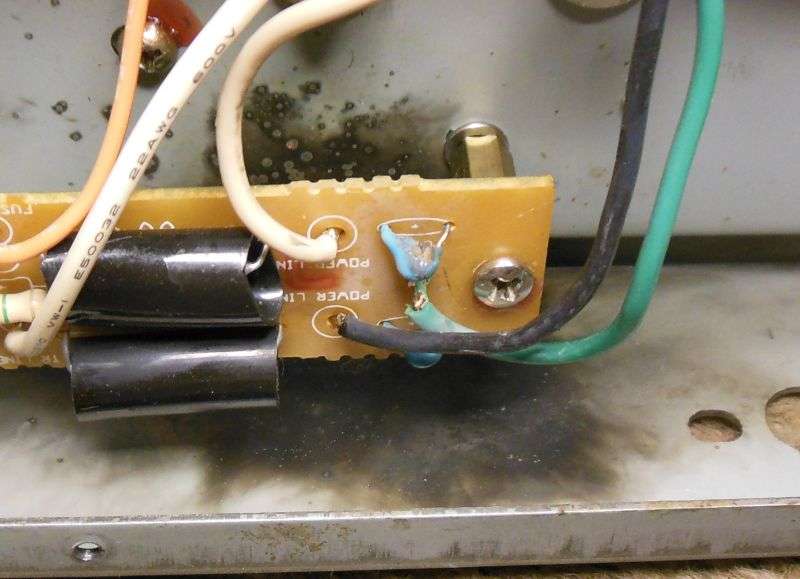
Hey, wait a minute... 8.53v-(.65 x 3) = about 6.6v. I think you have D71 in backwards if you are getting 6.6v at the ???anode??? with the transistor removed.
Might explain the symptoms too, because now that I think of it this way, it is acting like the base of Q33 is floating.
Might explain the symptoms too, because now that I think of it this way, it is acting like the base of Q33 is floating.
Last edited: