• You can now help support WorldwideDX when you shop on Amazon at no additional cost to you! Simply follow this Shop on Amazon link first and a portion of any purchase is sent to WorldwideDX to help with site costs.

Galaxy saturn ept360014b vr16 low power will not adjust

Hmm. Last I checked a DX99V was not a Saturn. The first "black" base radios had a high/low switch. The trimpot just behind the middle lever switch was the "low" set trimpot. When they later went to the front-panel carrier knob, this trimpot became the minimum-power set trimmer.

73
 
  • Like
Reactions: tecnicoloco
Hmm. Last I checked a DX99V was not a Saturn. The first "black" base radios had a high/low switch. The trimpot just behind the middle lever switch was the "low" set trimpot. When they later went to the front-panel carrier knob, this trimpot became the minimum-power set trimmer.

73
Sorry; my mistake.
Most of the 3600-14 chassis I'd worked on were like that.
Never have worked a Saturn myself.
Thanks for that info.
 
I'm having a similar problem.

Someone had put a 2312 and 1969 in as the finals. The radio will dead key fine up to 14 watts. Could not adjust vr20, but can now.

I readjusted the carrier cause that's too much key in my opinion.

I've replaced both finals with 2 brand new HG 1969's with matching hfe's of 125.

I've adjusted the power supply back down to 13.8v, it was up to 15.7v.

I can now adjust the bias on all trannys to 50ma each. I returned to rf stage and the normal tune. Still no more than 30 watts swing on AM and only 20 watts on ssb. The lights dim on ssb and really bad with loud modulation. The frequency display goes berserk when modulating on ssb.

The filter cap on the power supply side shows 10.69mf. The 2sb754 regulator runs pretty cool, even after hammering on it for a while. The audio ic and other regulator runs cool, slightly warm like the finals and regulator. Everything seems normal except too much modulation on ssb screws with the freq display and the lights dim out pretty bad. The meter lights dim slightly on AM but the freq display doesn't act a fool like on ssb.

No mods inside that I can see, it's the diode tied to the limiting resistor and r248 (I think) removed, that's it. Not a hacked up radio at all.

The owner states he used to get around 45 watts am swing out of it, and I have ran through several Saturn's that do over 40 on AM. But for some reason this one is being in pain in the rear.

Any ideas?
 
Variable power all the way down:

AM
Carrier = 1w
Swing (2 o'clock mic gain) =
Peak - 30w
RMS - 6w
Voltage drop = 12.8vdc
Lights dim slightly, no affect on freq counter

SSB:
Mic gain = 2 o'clock
Output
Peak - 18w
RMS - 18w
Voltage drop = 7.5vdc
Freq counter goes haywire and lights dim drastically

Variable power all the way up:
AM
Carrier = 8w
Swing @ 2 o'clock =
Peak - 25w
RMS - 7w
Voltage drop = 10.70vdc
Lights dim slightly, freq counter just fine

SSB
Mic gain @ 2 o'clock
Output
Peak - 15w
RMS - 15w
Voltage drop = 7.70vdc
Freq counter seriously affected, lights dim drastically.
 
Might want to make sure the Diodes are not Zeners - I know you can set it for 50mA - so how far does the trimmers have to be set - a typical normal Bipolar BIAS trim you'd be pushing it too hard if it's past anything before 9 o'clock and after 3 o'clock position - referring to Mid-point being usual.

Any extreme settings indicate problems with Bias circuit.

When Bias seems stable - the issue then focuses on the coupling between the stages - output to tank all the way back to even the pre-driver. Example being, it can "overdrive" the Driver - you'd know it by listening to the audio "clamping" on peaks - muffling up the sounds-likes by it being (appearing) very compressed.

IF they changed or took out caps to try and improve the sensitivity of the drive in SSB - fewer caps or wrong cap values can do this.

You won't experience this in AM or FM as much, but boy in the Spectral - there's a lot of spikes past 2nd.
 
If we theorize for a moment that TR43 failed at some point in the past and was replaced, you need only replace any innocent-bystander parts that got sideswiped when the final failed. Since the final tends to fail with a short from Collector to Base, this puts 8,10 12 or more Volts onto the base circuit.

L38, VR8 and D88 are common casualties.

Then again, taking the base and collector leads of TR43 loose from the circuit board would let you attach a cheap chinese transistor tester to those two leads. The third test lead would go to the circuit-board ground, where the emitter is still soldered. No need to take it loose to do this test.

Your problem will include one or more items on that list gone bad, most likely.

73
 
  • Like
Reactions: tecnicoloco
Tested the diodes in front of the driver and finals. Did in circuit test.

Driver diode - shows a value of 412 one way, shows OL the other way.

1st final diode - shows 0.010 one way, shows 0.010 the other way.

2nd final diode - shows 0.010 one way, shows 0.010 the other way.
 
What type of diode are those in front of the driver and finals? Mv1y? Will I have to order those, can they be ripped from another radio or can I use a different type diode in their place?
 
1N4148's work.

But you might want to retest your MV-1Y - they are ACROSS the Bias trimmers in the Finals.

The driver one is in SERIES with it - so it will only check one way.

upload_2021-9-13_9-51-50.png
The reason I'm asking you to recheck is due to the Parallel
design in the Final sections of Galaxy radios.
You may be measuring the trimmer across the Diode at the same time​

Try to use non-Schottky types, older package designs.

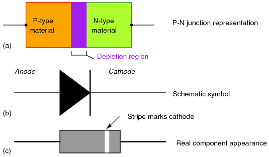
Schottky? Hmm - you may not know what I'm talking about but the older PN junction diodes work best for Bipolar because they are made similar - they both have a PN junction in them. Makes them more of a closer match.

03250.png

PN types above...
Schottky types below...
upload_2021-9-13_18-23-4.png

Schottky are simple SINGLE Junction diodes...

upload_2021-9-13_18-24-49.png
But you may not have the luxury of the older design versus what many import semiconductors are now, Schottky types - meaning they are a simple N layer with a weld, forming a narrow junction - which LOWERS the voltage drop across them making them more efficient in passing current and switching - but not for Biasing.

The (older) PN junction has a higher voltage drop - which is what you want to use to help the transistor keep the Bias region forward-biased - so that means the Schottky are not as effective in your bias fix.

Edits: Fixed Graphic...

Wanted to also pass along;
this post is not just directed at you, it is also for others that may stumble across this someday in the future and wonder what Schottky and PN meant...:)
 
Last edited:
  • Like
Reactions: tecnicoloco
Will check that in a bit. Thank you for that info, and yes I know what a schottky diode is, but thank you for the extended info.
 
I just lifted the leg of one of the diodes in front of one of the finals. I tested that diode again with one leg out of circuit, it shows a short both ways.

I lifted one leg of the other finals diode and tested it with one leg out of circuit, it too shows a short both ways.

I lifted one leg of the diode in front of the driver and tested it with one leg out if circuit, it shows fine, a value one way but OL the other way.

Guess the diodes in front of the finals are shorted and I should replace those.

I looked up last night these diodes and what type they are. Found that the dx 77hml has the same board layout and parts. The parts list states these diodes are nothing more than zener diodes @5.6v - 0.5w. I also learned I can just use a 4148 diode in its place.

Just curious of something though. The 77hml has the same diodes, but they aren't across the front of the trannys, they are mounted on the trace side of the board just jumping the same locations. Why the need to mount them on the trannys then?
 
And be careful.

Know that MOSFET requires the diodes to be Zeners - with their Bands TOWARDS to the GATE lead.

Bipolars - Know that they can use Zener, or Standard PN (1N4148 / 1N914) but Banded end to Foil Ground (Emitter Leg)

One requires itself to be Reverse-Biased for regulation - while the other provides regulation thru forward Conduction
 
  • Like
Reactions: tecnicoloco


Zener diodes acts like normal P-N junction diodes under forward biased condition (Cathode (band)) end to ground.
When they are reverse biased (Anode or non-banded) end to ground, they act like a normal P-N junction diode too (no current or high impedance), until they hit their Zener voltage, then they start to conduct, or clamp down and hold at the Zener voltage.

https://www.physics-and-radio-elect...-definition-vicharacteristics-breakdowns.html
 

dxChat
Help Users
  • No one is chatting at the moment.
  • dxBot:
    Tucker442 has left the room.
  • @ BJ radionut:
    LIVE 10:00 AM EST :cool:
  • @ Charles Edwards:
    I'm looking for factory settings 1 through 59 for a AT 5555 n2 or AT500 M2 I only wrote down half the values feel like a idiot I need help will be appreciated