• You can now help support WorldwideDX when you shop on Amazon at no additional cost to you! Simply follow this Shop on Amazon link first and a portion of any purchase is sent to WorldwideDX to help with site costs.

Galaxy saturn ept360014b vr16 low power will not adjust

Well, I yanked those 2 out. Got the old diodes off the wafers. Super glued 2 4148's on the wafers. Letting them sit right now.

Will this work as it should for normal cb use or are the 4148 diodes meant only for temporary use?
 
Biased correctly - they'll last forever - or until the next one that owns it does something (wrong) to it.

Setting the mA "draw" the Transistor uses - properly - will keep the part "set right" to do it's job and when operated and used like you would with an ordinary CB radio (Red this as : Don't Get Stupid With It) The radio will last a long long time - possibly longer than your lifespan.

Remember - when you have MV1Y - they are mounted like they were installed.
 
Still the same. Had to readjust the bias slightly, but still same problem.

AM = low power

SSB = low power, lights dim pretty bad and freq counter goes haywire.

2sb754 regulator staying slightly warm.
Audio IC staying cool
Other regulator staying cool
Finals and driver staying cool/luke warm
Bridge rectifier staying cool
Filter cap testing at 10.69mf (labeled as 10000uf)
That's after hammering on it on ssb and am.

Driver set to 0.05a (equals 50ma)
Both finals set at 0.05a each (equals 50ma each) totaling 0.10a (equals 100ma). My meters ma gauge isn't working, but the amp gauge does.

Any suggestions?
 
Check - locate the OUTPUT cap - the one that takes all the RF generated in that Driver and Final Section - thru a coil - into the output network - might want to swap out that cap with another one to see if the cap has failed.
upload_2021-9-18_22-20-36.png
Depending on the year the radio was made, the Silver Micas can blow - oftentimes as a dead short to RF but not DC (arcing) - so if you have another cap - a simple disc type of similar value and rating (100V min) - try it to see if it will recover.
 
Would something in the rf section cause all the lights to dim drastically and the freq counter to go haywire?

Only thing that gets hot on the radio is the power supply regulator mounted on the back top corner behind the power supply. Voltage from power supply to main board drops to around 7.5vdc on ssb with modulation and around 10vdc on AM with modulation. Is there a known issue with the power supplies in these radios that I should look at?
 
The problem lies in a potential short to ground.

What are your RF power levels showing? Low power - or Rises then "holds".

Might want to "tap" the 8V regulated power supply. Monitor it from several taps - see where the "sag" begins - even the TX side back towards the Pre-Driver and monitor there too.

There may be a problem with the 4558 Mic Amp - TX / RX switch IC - IC 3 - although unlikely because you are able to even key the radio - it's when it runs a high current demand mode like SSB and even with voice peaks - which shouldn't make it act this way - it does this "thing" - so look at the main Regulation output at the Regulators own (8V constant) output - and while you can do this - check the TX voltage (TX Switch supply) and see if it' "drops out" as you continue this test
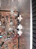
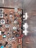
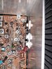
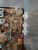
  • - if so - you may have problems of it needing a good tune up and possible cap recheck and replace - for the TX 8V should remain steady during the keyup and even when your yammering and yelling into the mic. Voltage sags are a chronic problem with these radios usually caused by bad soldering; from simple cold solder onto the test point jumper mirror board can short to the jumpers UNDERNEATH and generate this condition - reflow solder around this section and look for potential shorts and even pockmarks from arcing
upload_2021-9-19_11-19-51.png
Although SMD - good example of what to look for​

Can you adjust ALC and AMC and does the power level show any changes - AM/SSB?

Once AMC an ALC can be ruled out as part of the problem, the condition is with the "RF amp" or TX Strip or RF Deck - depending on your interpretation of the function.

How? Several ways, one mostly being bad coupling between stages.

Since this is affecting the power supply - to blame the power supply - prove it - simply remove the jumper and install instead, a jumper wire clip to jumper from the AM Regulator post to the Driver or Final test point post - using a Dummy load on the Antenna jack, to isolate the problem either as a bad Transistor (could be an MOSFET installed in error) or bad soldering onto open trimmer pot that lets all the bias into the Transistor it's designed to trim.

You're getting 50mA and it's adjustable. So - by your word, this rules out the MOSFET and trimmer problem - so we can only presume to continue with the above steps to rule out one section or another - if the lights "continue to dim" even while jumpering one section versus both from the same (the Mirror board test strip jumper) - but yet it (Dimming wacky performance) doesn't occur when NOT jumpered or even when the other section is jumpered nothing happens - during this test, the bad section is; the one you're jumpering causing the lights to dim.
 
  • Like
Reactions: tecnicoloco
Just got around to removing the disk like capacitors in front of the finals. One is c167, the other is c2??. In circuit they both showed as dead shorts on my dmm set on the short sound, but out of circuit they show nothing, no resistance or anything. I placed them in my parts tester (longrunner) and both showed as bad or unknown part on the screen.

Since it seems as though these caps are open, and not shorted, then why am I showing shorts in the final section? Something else could be shorted or its prolly based off the circuit in test?
 
  • Like
Reactions: Handy Andy
Yes, the easiest way to determine that is to unsolder the Final legs that mount to the board, break the connection and re-test. - orienting the leads both ways to test polarity, positive and minus then reversed - to check for the KIND of short it could be - Diode - would show infinite one way nearly dead short the other - while resistive would be a short BOTH ways signaling a solder blob or bridged solder somewhere
 
  • Like
Reactions: tecnicoloco
I have a similar problem I am seeing 40 watts Am but 20-25 watts Ssb and a slight dimming I have own Saturn's and 2980 and the output was 30+ on ssb.i Am a bit lost as the Am is fine ssb is low I have adjusted L40, L42, L43 and L44. Also I have adjusted v12 no change
Where should I look.i also have seen in some Saturn's the were 2 or 3 disc caps near the finals I think one was C170 and one had a value of 560pf..
 
  • Like
Reactions: Handy Andy
The output section - the one where that 3-way coil combiner is at, has been known to blow those caps - low power is one of many symptoms - and dead finals are the result - that when you replace them, if you don't do the same for the caps , they are already compromised from the wattage dissipation (overheating) you get failed finals again and even worse problems after....

The 20~25 watts SSB and dimming is a red flag on BIAS adjustment - shut it down and work the TP 7, 8 and 9 stuff and reset the bias to a little less mA setting than you originally had. - and see if this tweak will clear that up.
 
  • Like
Reactions: tecnicoloco
Any particular parts to focus on..I adjusted the bias and the dimming went however as stated before Am power is about 40watts and 16/18 avg. watts bird 43.
I will send u a picture of the first saturn I had and it has 3 capacitors on the bottom
 

Attachments

  • Screenshot_20211102-202223_Chrome.jpg
    Screenshot_20211102-202223_Chrome.jpg
    760.9 KB · Views: 14
  • Screenshot_20211102-202214_Chrome.jpg
    Screenshot_20211102-202214_Chrome.jpg
    640.2 KB · Views: 15
The 561 - both of these are are two leads but in different positions...giving you different performance...

upload_2021-11-3_8-34-31.png

There is a big difference...

upload_2021-11-3_8-27-52.png

One "sees" a cap directly on the Base...

The other, only has a cap on the BIAS to the base...

One - the one of the left, will change the amount of power the transistor on the left will produce.

The one on the Right - will be unaffected - but it's BIAS will have some RF filtering - which may not amount to much depending on how much isolation (buffered source of power) the BIAS is from the RF signal line going in.

Check for heat and see if one of these parts is getting too hot - more than likely it is the one that doesn't have a cap on the BASE but on the BIAS line.

This would help explain the discrepancy in SSB - for one transistor is driven harder than the other - making it SATURATE and LOSE power faster with higher gain signal (SSB full power single) arriving to be amplified.
 
  • Like
Reactions: tecnicoloco
Look at the diagram
C170 - 560pf
C210a-.047uf
C505- ,.O1uf

U mentioned 2 capacitor they are actually 3 I should have given the values..look at pictures I uploaded
 

Attachments

  • Screenshot_20211102-202223_Chrome.jpg
    Screenshot_20211102-202223_Chrome.jpg
    760.9 KB · Views: 17
  • Screenshot_20211102-202707_Chrome.jpg
    Screenshot_20211102-202707_Chrome.jpg
    406.6 KB · Views: 16
Ok, the original photo looks liek one cap - has a leg on the Bias line...


Remove the 561 and try again.

Don't know what the TOPSIDE shows or has in conjunction with these components.

Again - if one Final or the jumper to BOTH finals has more capacitance than it shoudl AM would work, but SSB will suffer...

Again, need to know topside too - you can show me these caps - and I can only guess the values they are supplanting them with on the top side of the board and if any are even installed - I see leads of soldered pads so I know there's something up there - just no idea as to their values to even give you a direction to take?


The Driver - 103? again on the BIAS line - it may not bee (Bee? Gosh Darn It!) BE needed so remove and retest...

Again, will have to see what you have on the topside - BIAS diodes - stuff like that...
 
Last edited:
  • Like
Reactions: tecnicoloco
See photos
 

Attachments

  • 20211103_201831.jpg
    20211103_201831.jpg
    1.7 MB · Views: 13
  • 20211103_201824.jpg
    20211103_201824.jpg
    1.7 MB · Views: 12
  • 20211103_201714.jpg
    20211103_201714.jpg
    1.8 MB · Views: 11
  • 20211103_201657.jpg
    20211103_201657.jpg
    1.4 MB · Views: 12

dxChat
Help Users
  • No one is chatting at the moment.