• You can now help support WorldwideDX when you shop on Amazon at no additional cost to you! Simply follow this Shop on Amazon link first and a portion of any purchase is sent to WorldwideDX to help with site costs.

Grant XL having problems!!

1jonnyz

Member
Dec 30, 2011
62
3
18
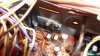
I picked this Grant XL up at a hamfest for a great price but am having problems getting it aligned... I am using these alignment instructions
The Defpom Grant XL (PB-208AA) alignment page

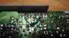
When I first put it in my truck the tx and rx were not that great, I figured it needed to be aligned. I have the equipment to do it although I am pretty new to this. When I started messing with it I found some problems... BTW, this has the PB-208AD board in it.

I can not get the ch19 AM adjusted to 34.9815MHz, the closest I can get it is 34.9895, and the slug is all the way out. I can get it tuned with the clarifier however.

I get .790Mhz on Ch1 AM and it is supposed to go up 10Khz a channel then, but I have several channels that stay the same as I change channels.

What is really bothering me is that when I test the mA at TP 7 & 8 I get nothing at all.

I discovered today that the clarifier does not work for channels 1 through 8, and channels 9 and 10 the clarifier doesn't work on AM, only on LSB and USB. Any channels higher it works fine on LSB, AM, and USB???

It doesn't appear to have any major changes made to it... I did put in a 2n6487 AM regulator, schottky diodes, Q14 to 2sc2999, and upgraded some of the electrolytics.

I would REALLY appreciate anyone's help here as this is a nice looking radio and I would really love to get it working right! Thanks!!!

Jon
 

Adjust for 34.3515MHz (New Zealand).

Adjust for 34.985 MHz (FCC).

Alignment:
http://www.cbtricks.com/radios/cobra/148gtl/graphics/cobra_148_gtl_sm_pg48_pg63.pdf

Seen this before. If the clarifier has been opened up to slide 5 khz or more; then the clarifier will have a different center slot off of the center position; that is why you can find the right freq at the right spot on the clarifier. Once you establish the clarifier position that allows the coils to all agree, then align the radio the rest of the way using the link above.

The reason ch 1-8 do not work is because the pll is unlocked due to the wrong VCO voltage setting. Just use the voltage setting on the alignment page I provided and they should work. That is the most common fault. Other faults may be either the tripler inductor is out of adjustment, there may be dirty contacts in the rotary ch switch, bad solder joints from the ch switch to the board, or a possible failure of the pll itself. Usually, it is just the VCO voltage out of spec.

Have no idea how many hacks have been done to this radio, so you may/may not need more help to get it right. Personally, I would also unhack the clarifier so that it only slides +/- 1khz, as this will not only re-establish the center slot but keep it from drifting in cold/hot temps too much.

BTW - if the radio has output wattage; then you must be doing the mA test setup incorrectly. POS lead of the DMM (mA/DC mode) goes to the post/voltage feed on the board and the NEG lead goes to the wire that came off of that post. One of those wires will go to the left rear of the radio chassis ('driver') and the other will go to the right of it ('final'). Far left corner vr is the driver adjust and to the right of it is the final vr adjust. Test and adjust in USB or LSB mode only, making sure the mic gain is set to 0 first before keying the mic.

BTW#2 - Its a solid tip not to modify a radio BEFORE you are sure that everything in it is working 100% first!
 
Last edited:
I checked this and there is no changes to the clarifier. All of the mods had wires switched around on the knob but this has 3 wires that go straight to the board.

I got the VCO voltage right on the money. Had the clarifier at 12:00 and got the CH19 AM, USB, LSB right on the money. I went to the next step and got 7.7985 on LSB, and 7.8015 on USB. When I checked Ch19 AM TX mode I got 27.185 and I noticed the red transmit light wasn't coming on. I tried the PA and got nothing. I checked the back of the board and found a jumper wire that was broken off of IC8, or I think it's IC8. It looks like it's pretty new as the solder is pretty fresh, and pretty sloppy! I soldered it back on but still nothing. I also get nothing in the way of mA on TP 7 or 8, positive to post and negative to wire. I tried that with a UEI DM 393 and a BK 2709B and nothing.

I'm stumped!
 

Attachments

  • P1010917.JPG
    P1010917.JPG
    1.9 MB · Views: 16
  • P1010916.JPG
    P1010916.JPG
    2.1 MB · Views: 17
IF the radio has power output (4-16w) on AM and SSB; THEN you are still doing something wrong. Case closed. Can't have one w/o the other.

Connect your freq counter to test point #1, check ch 1/19/40 and see if any/all of them are on freq or going all over the place. If the freqs are going all over the place ('unlocked'); then the VCO voltage or the tripler inductor are out of adjustment and then the pll will become unlocked. Also check for broken wires on the mod switches, as this may also cause the pll to become unlocked.

Why did you think it was a bargain? Someone else couldn't fix it. Hang in there.
 

Attachments

  • 148pcb.gif
    148pcb.gif
    6.5 KB · Views: 43
One more thing... when I key up the mike the carrier swings to about 10 on AM, after a second or two it drops down to about 6 and the needle starts bouncing between 5 1/2 and 6 1/2 on my wattmeter and the meter on the cb, like it's oscillating?? Don't know what that's about!
 
almost sounds like the AM regulator is going bad or not making a good connection 100% of the time.. without seeiing what the radio is really doing it could be oscillating causing the power to jump up and not the regulator.
 
  • Like
Reactions: Robb
I have no output power at all. I did get the oscillating to stop however. With the carrier alignment I have LSB and USB on the money, when I tx on 19 AM it is supposed to be 7.8 Mhz but I am showing above 16 Mhz. Also when I key up I get backwards swing on the cb meter, the Hitachi watt meter doesn't move at all, it stays on zero. And I still get nothing in the of mA on TP 7 or 8, and yes I am doing it correctly. Thanks for the help!!
 
If you have power output, but are getting no reading when trying to set the driver and final bias, Then you are not doing it correctly. Either your connections, the meter itself, or the meter settings are wrong.
To set the driver and final bias, the wires at TP7 and TP8 have to be disconnected and the DCMA meter connected in series between the wire and the test point. If you are using an analog meter, the meter lead connections between the wire/TP must have the proper polarity.
Also, if the clarifier had been modded, the wires on the clarifier control will be unchanged, but there will be circuit changes on the main board .
It does look like someone did a real hack job on this rig. Good luck and 73s.

- 399
 
Last edited:
I have two meters, a BK 2709B and a UEI393. I tried on both of them and nothing at all. Positive to post negative to detached lead, positive on meter to mA socket, meter set at mA, key up and nothing at all on either post. The clarifier has not been modded. I checked and saw 4 or 5 ways to mod the clarifier and none of the parts that need to be removed have been removed, they are still there, and nothing has been modded on the clarifier knob. The wires from the knob still go directly to the board through a plug.
 
Now I'm back to keying up and get a carrier then a few seconds later it starts oscillating, meter starts at 6 and then drops down and bounces between 2 and 4. When I was recapping, I replaced c172, an electrolytic next to the transformer, and I noticed D44 was broken. I don't know if I broke it or whether it was broken. At any rate, I replaced it with a 1N4742A Zener. I know that's not what it should be, I can't read on the schematic what it should be, looks like m218-3?? I am wondering if this is the wrong diode I put in, would that cause this weird problem I'm having?
 
D44 requires a 18v zener diode and that is part of Service Bulletin #1226. So put the right diode in it.
http://www.cbtricks.com/radios/cobra/140gtl/graphics/cobra_140gtl_142gtl_148gtl_tb1226.pdf

I agree with Sonoma; re-solder the AM Regulator joints too for good measure.

So if you are seeing meter movement when the radio is oscillating; then what you are saying is that it has power output. OK; let's back up a little bit here. Try checking the voltage; not mA on TP8/9. You should see +8v. Have no doubt you will see it.

If the RX/TX light doesn't turn red when TXing; then something in the pll circuit is still not right and it is unlocked still.

Put your freq counter back on TP1 and key the mic. Does it show the same freq as it did in receive mode? if so; then the pll/VCO/loop osc should be OK.

Just because the clarifier plug is unmolested; that doesn't mean that a trace on the bottom side of the board hasn't been cut or a wire added to get the +8v.

BTW; what mods does this radio have in it - all in?
 
Last edited:
Hi Robb, The only mod now is the Schottky Diode upgrade that I did.

Thanks for the service bulletin! I have a few Cobra 29 LTD's sitting around, do you know off hand if they have the Zener I need? I believe they also have the MB3756, I could borrow them until I get some in the mail. I will check the other stuff after my shower and get back to you.
 
No; the 29's don't have the mb3756. That 18v zener is an upgrade that is necessary for radios that use the mb3756. No; the 29 doesn't have that zener in it. Not as though it is an expensive part;
 

dxChat
Help Users
  • No one is chatting at the moment.
  • @ BJ radionut:
    Hamvention this Weekend!!!!~ See link above
  • @ nomadradio:
    Hello from Dayton. Well, okay. Kettering.
  • @ ShadowDelaware:
    Wow I did not know this was here until just now
  • @ c316buckeye:
    no conditions in ohio