• You can now help support WorldwideDX when you shop on Amazon at no additional cost to you! Simply follow this Shop on Amazon link first and a portion of any purchase is sent to WorldwideDX to help with site costs.

Hello from Germany , problem with my CB Sommerkamp TS 790 DX identical Galaxy Pluto No TX Power RX OK

CB-Whisky

Member
Apr 14, 2022
7
0
11
62
Hello from Germany , I have a problem with my CB Sommerkamp TS 790 DX identical Galaxy Pluto no TX power RX ok. The Driver 2SC2166 and Finals 2SC2312 replaced TP 8 with carrier AM 3,5 V SSB 12,5 V can somebody help ? Still no TX output Analyser Peak - 0,7 dBm with replacement Driver and Finals
vy 73 Werner
 

Attachments

  • 20220413_154144.JPG
    20220413_154144.JPG
    125.6 KB · Views: 20
  • 20220407_173108.JPG
    20220407_173108.JPG
    81 KB · Views: 17
  • 20220414_205604.JPG
    20220414_205604.JPG
    131.7 KB · Views: 17
  • 20220414_205533.JPG
    20220414_205533.JPG
    110.5 KB · Views: 18
  • 20220414_211637.JPG
    20220414_211637.JPG
    102.5 KB · Views: 18
Last edited:

two questions first.

are you able to set the bias on the driver and final to specs?

do you have an oscilloscope or another way to measure RF voltage?

if you have a scope, we might be able to guide you through the TX stages to see where your signal is getting lost.
LC
 
  • Like
Reactions: sp5it
two questions first.

are you able to set the bias on the driver and final to specs?

do you have an oscilloscope or another way to measure RF voltage?

if you have a scope, we might be able to guide you through the TX stages to see where your signal is getting lost.
LC
Hi ,
Thanks for your fast response
1. question: yes I can measure the Voltage on TP 8 to the Driver and change the Voltage with VR 13 and VR 12
Sorry for my bad English , is that what you meant ?

2. question : I have a new Digital Osci but its a struggle working with it


Thanks for all your help I am a novice and thanks for your patience

73 Werner
 

Attachments

  • 20220415_120824.JPG
    20220415_120824.JPG
    95.4 KB · Views: 11
Last edited:
I caught your PM, sent you another back, but here's the MIXER voltage chart and some other data.

Since you have RX, you should also look for TX 8V - the "rail" that supplies the power to the Mixer, also feeds the Pre-amp / Buffer (you have two) stages.

1650150511114.png
1650150917612.png
The "IC9" - is this guy...
 
What I would check first is to remove the bias-test jumper ("mirror") board. Set the radio to either sideband with the mike gain set to zero. There are three contact posts that supported the jumper board. A CURRENT (not volt) meter gets the positive lead clipped the post nearest the center of the radio. The negative probe clips to the center-most of the three posts to measure final-transistor idle current with the mike keyed. The outboard post is to measure the driver transistor's zero-signal idle current. We set the driver trimpot VR11 to 60 mA. The finals get turned first for a zero reading. One final trimpot is advanced to read 60 mA, the second one set to bring it up to 120 mA. VR20 and VR10 can be set in either order, just so each one has contributed 60 mA to the total reading.

This is an unnecessarily long way to indicate that the reading obtained from this set of test points is also a diagnostic. If any of the three bias adjustments fails to produce a result, this points to a failed component in that circuit. And if all three of them adjust properly, the problem is elsewhere.

Troubleshooting is a process of elimination. Seeing that the DC-circuit behavior of the driver and finals removes one possible fault from the list of possibilities.

And if one or more of these reads only zero current no matter what gets adjusted, this will point to part or maybe all of your problem.

It would be useful to know if the removed driver and finals were tested. If they test failed, this points to related components that can be damaged.

And if any of them test good, this is also useful information.

73
 
Last edited:
Thank you soo much i appreciate for all your help i will check the Voltage and mA after Easter holidays
I wish you all a Happy Easter

vy 73 Werner
 
Last edited:
It seems my description of how to check and adjust the idle current in the driver and final transistors was a bit breezy and lacking important detail.

Or so I am told.

So I'll try to break it down a bit further.

Just to start, we are measuring the current drain first of the driver transistor, and next in the final transistors. In SSB mode, you should not see any power come from the transmitter until you speak. There is no continuous carrier while the mike is keyed, only a modulated signal in step with your voice.

The "idle" current in question is a small trickle of DC current that needs to flow in the driver and final before any drive signal arrives to them. This is not needed for AM mode, the AM carrier takes care of this for us.

The setup is to first turn the mike gain to zero. Prevents room noises from disrupting the reading. Choose one sideband mode, either USB or LSB. Doesn't matter which.

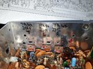
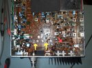
Unplug the jumper that completes the power circuit to the final and driver. Radios made by RCI have a small double-sided piece of circuit board held between three fork-shaped spring contacts. Pulling it out cuts those two circuits. It is commonly called the "mirror" board, for visible reasons.

The only way to measure a DC current is to break the circuit we wish to measure, and then complete the circuit THROUGH the meter. Clip the meter's positive probe to the fork contact that is nearest the center of the radio. It will remain there until the meter is unhooked and the jumper board is put back.

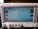
First, the meter's negative clip goes to the fork contact nearest the outside of the radio. This one leads to the driver transistor's collector circuit. Set the meter to read 2 Amps DC or less. Key the mike and adjust VR11 for a reading of 60 mA, or "0.060 Amps". The control should reach both higher and lower readings when turned up or down. An old radio will have front panel controls that are "scratchy" and produce noise when turned. The small trimmer pots can also become noisy this way. If the reading is erratic when the trimpot is turned, a tiny drop of control cleaner should help. If it won't help, that trimpot may be worn out and need to be replaced. If the surface if the trimpot is visibly corroded, that will be a problem. We routinely find these trimmer pots to be worn out in radios over 20 years old.

For now we'll assume that the driver adjustment went smoothly. If it did not, there is a fault that needs troubleshooting.

Move the meter's positive lead to the center of the three fork contacts. Now key the mike and set each trimpot VR10 and VR20 for a zero reading. If you can't achieve that, a trimpot may be bad, there might be other trouble, or both.

We'll assume you now have that zero reading. Advance VR10 until the meter reads 60 mA. Now advance VR20 until this reading doubles, to 120 mA.

If that step fails, more troubleshooting will be in order.

And if all three settings succeed properly, this reduces the list of possible causes for the problem.

A failure to achieve those current settings points to trouble in the power circuits, the driver and final. And if those settings all work like they should, the failure is most likely upstream from those stages.

73
 

dxChat
Help Users
  • No one is chatting at the moment.
  • dxBot:
    Tucker442 has left the room.
  • @ BJ radionut:
    LIVE 10:00 AM EST :cool:
  • @ Charles Edwards:
    I'm looking for factory settings 1 through 59 for a AT 5555 n2 or AT500 M2 I only wrote down half the values feel like a idiot I need help will be appreciated