So i got my new Oscilloscope and want to see how it works. I was told all i needed to do was to hook it up
to my dummy load and i could test it on my CB. Then i was told no that could/would burn it out. Then i was
told i could hook it to my antenna switch to port 3, port 1 has my antenna, port 2 my dummy load and port three is
unused. Then a Ham radio user told me i had to use a RF sampler, which looks like it would be smarter? Part of the problem
is i am worried about running out of time it it is not working right as its from Amazon and i have already lost a couple of
weeks due to you know life and family taking time away from hobbies you know how unfair of my family just kidding. So i did look
around the forum and did see older postings about samplers but the pictures of them or schematics were to old to be viewed now.
Is it safe to hook my scope direct to stock wattage CB to test? Is it safe to hook to a dummy load? or is it safe to use the open port
of my antenna switch with a legal 4 watt radio? If i must use a RF sampler is this one from Ebay look ok to use it this is the only safe
way to use my scope?
 Or is this one a better option?
Sorry for so many questions i am so wanting to check the Oscilloscope out but i do not want to smoke it right up the first time i use it.
I thank you for reading and await your wise responses.
to my dummy load and i could test it on my CB. Then i was told no that could/would burn it out. Then i was
told i could hook it to my antenna switch to port 3, port 1 has my antenna, port 2 my dummy load and port three is
unused. Then a Ham radio user told me i had to use a RF sampler, which looks like it would be smarter? Part of the problem
is i am worried about running out of time it it is not working right as its from Amazon and i have already lost a couple of
weeks due to you know life and family taking time away from hobbies you know how unfair of my family just kidding. So i did look
around the forum and did see older postings about samplers but the pictures of them or schematics were to old to be viewed now.
Is it safe to hook my scope direct to stock wattage CB to test? Is it safe to hook to a dummy load? or is it safe to use the open port
of my antenna switch with a legal 4 watt radio? If i must use a RF sampler is this one from Ebay look ok to use it this is the only safe
way to use my scope?
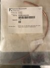
RF Sampler Modulation monitor - See your signal - 1-30 MHz for Ham and CB Radio | eBay
Do you want to view or monitor your transmitted signal, either to a dummy load or your antenna system?This RF Sampler or sampling port is designed to sit in-line with the transmitter and other components of the transmission line before the antenna.
www.ebay.com
Sorry for so many questions i am so wanting to check the Oscilloscope out but i do not want to smoke it right up the first time i use it.
I thank you for reading and await your wise responses.


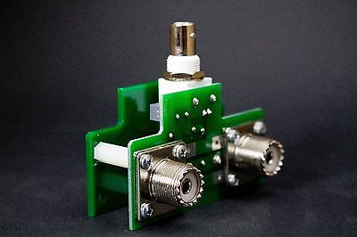
 ). I believe my total cost was about $7.00 (for the solid coax) and using junk box parts.