After talking to Marconi who has given me valuable info I thought Id post a pic of the damaged wafer in my CLR2 antenna ]. Hi Gain does not have a replacement let alone literature on this antenna. Still hoping I can come up with a fix for this so as not to scrap it.ATTACH]13425[/ATTACH

You are using an out of date browser. It may not display this or other websites correctly.
You should upgrade or use an alternative browser.
You should upgrade or use an alternative browser.
-
You can now help support WorldwideDX when you shop on Amazon at no additional cost to you! Simply follow this Shop on Amazon link first and a portion of any purchase is sent to WorldwideDX to help with site costs.
-
A Winner has been chosen for the 2026 July 4th Retevis RA89R Giveaway! Click Here to see who won!
Help
- Thread starter Mr T
- Start date
I'm somewhat of a layman so where would I begin?
Mr T, this is not where you will begin, but maybe I can help. If you're considering trying to make the coil I posted earlier, then maybe you need to talk to "The DB." Let me know if this is the coil you are considering, or is it the disk setup you have.
I think it is DB that seems to understand the math on antennas and matching pretty well. If it is not DB, then I believe there is another member that claims to understand a lot of math for antennas and matching.
All I can do is try and measure the dimensions as I physically see the setup, and I can figure out pretty close the overall length of this wire using the math that I can get to Calculate the Circumference of a circle, on the Internet. I believe this wire is somewhere near 33" inches long in total...given >1" inches maybe.
Can you make out or imagine how the wire winds its way from bottom to top in the images I posted earlier? If not, I'll try and get some better pictures if that might help. My camera will not let me get really close up though.
Let me know if this is the way you would like to go, and I'll see what I can do to help.
Last edited:
Once again Thanks Marconi
Not really interested in replacing the disk since it has such a low power rating and if I could make the coil, I think it would do a better job.
I can see the basics of the winding on the coil u posted but there are some in's and out's on the winding that I cant really make out. I assuming the ends of the wire itself connect to the SO center and shield. I can follow written instructions better than trying to dissect pictures. But pics do help.
Really hate to give up on this since so much of this antenna is in such great shape. Besides , being unemployed right now I have a lot of time on my hands.
Once again Thanks Marconi
Not really interested in replacing the disk since it has such a low power rating and if I could make the coil, I think it would do a better job.
I can see the basics of the winding on the coil u posted but there are some in's and out's on the winding that I cant really make out. I assuming the ends of the wire itself connect to the SO center and shield. I can follow written instructions better than trying to dissect pictures. But pics do help.
Really hate to give up on this since so much of this antenna is in such great shape. Besides , being unemployed right now I have a lot of time on my hands.
Ok, I'll try and come up with some better images. I took the matcher out of the hub, and that will allow me to get better images of the wire and PVC coil former. If I can't get some close-ups that are clear that is best, or if not I'll do a drawing with the dimensions as I see them.
Last edited:

Here's some old adds on the CLR2 (CLR-II) antenna. Last add states maximum power is 300 Watts. Must be small wire on the inductor I presume. I would also venture to say this is a 5/8 wave radiator and likely had a shunt fed coil to bleed static. Just a standard 5/8 wave loading coil arrangement.
http://www.cbtricks.com/ant_manuals/hygain/model_473/ad/index.htm
Marconi, is there a dead short from the center pin to the shield of the UHF female connector? If so it would confirm my suspicions.
http://www.cbtricks.com/ant_manuals/hygain/model_473/ad/index.htm
Marconi, is there a dead short from the center pin to the shield of the UHF female connector? If so it would confirm my suspicions.
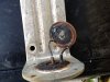
After talking to Marconi who has given me valuable info I thought Id post a pic of the damaged wafer in my CLR2 antenna ]. Hi Gain does not have a replacement let alone literature on this antenna. Still hoping I can come up with a fix for this so as not to scrap it.ATTACH]13425[/ATTACH
Can you take another photo and make it a close-up of the failed coil?
Can you take another photo and make it a close-up of the failed coil?
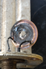
Robb, here is a better picture that was posted by regencycb in another CLR2 thread.
Below we can see this disk coil. IMO it is the same circuit as the wire coil I posted for Mr. T.
Here we can see the circuit is all one wire starting at the ground side of the SO239, and the wire ends up in the middle of the disk, and the disk is screwed into the middle of the inside of the hub. This is where the matcher wire ends and connects to the radiator sitting on top of the hub.

Note that the center conductor is connected at a tap point that is about 1.25 coils from the start, and the rest of the foil continues all the way to the radiator uninterrupted.
Last edited:
Here's some old adds on the CLR2 (CLR-II) antenna. Last add states maximum power is 300 Watts. Must be small wire on the inductor I presume. I would also venture to say this is a 5/8 wave radiator and likely had a shunt fed coil to bleed static. Just a standard 5/8 wave loading coil arrangement.
http://www.cbtricks.com/ant_manuals/hygain/model_473/ad/index.htm
Marconi, is there a dead short from the center pin to the shield of the UHF female connector? If so it would confirm my suspicions.
This matcher does show a continuity between the antenna and the feed point.
.jpg")
Robb here is the best one I could get for now. And again thanks for everyones help..http://www.worldwidedx.com/attachment.php?attachmentid=13448&stc=1&d=1403009505
This antenna was given to me so I don't know exactly how much wattage was sent thru it.
This antenna was given to me so I don't know exactly how much wattage was sent thru it.
Attachments
T, in my professional opinion your antenna matching system is toast.
Here are some more images I took closer up.
.jpg")
.jpg")
.jpg")
.jpg")
I can't describe the wires and the holes they go in right now...I don't have time. This looks simple, but it would probably get very complicated fast if you didn't have a good reference guide with all the right dimensions. You sure don't want to be doing trial and error on this setup.
Here are some more images I took closer up.
I can't describe the wires and the holes they go in right now...I don't have time. This looks simple, but it would probably get very complicated fast if you didn't have a good reference guide with all the right dimensions. You sure don't want to be doing trial and error on this setup.
Last edited:
Thanks Marconi for the pics. Yes it looks simple and complicated at the same time. As in, looks like 3 wires from the SO and Im assuming the same 3 go to the radiator of antenna but where does the single [shield side] tie into the 3 wires at to complete the circuit showing the dead short? I really don't expect anyone to tear one apart just to see dimensions. That's why I keep hoping some one has it written down already.
Thanks Marconi for the pics. Yes it looks simple and complicated at the same time. As in, looks like 3 wires from the SO and Im assuming the same 3 go to the radiator of antenna but where does the single [shield side] tie into the 3 wires at to complete the circuit showing the dead short? I really don't expect anyone to tear one apart just to see dimensions. That's why I keep hoping some one has it written down already.
I've already described it in words, but when I did it I was trying to add some dimensions as I went. So I'll have to do it over, and I can't get to it today. I'll also get some additional pictures for the end of the wire that connects to the radiator. I took the matcher out of the hub and that makes it a bit easier to photograph and measure.
dxChat
- No one is chatting at the moment.