
You are using an out of date browser. It may not display this or other websites correctly.
You should upgrade or use an alternative browser.
You should upgrade or use an alternative browser.
-
You can now help support WorldwideDX when you shop on Amazon at no additional cost to you! Simply follow this Shop on Amazon link first and a portion of any purchase is sent to WorldwideDX to help with site costs.
-
A Winner has been chosen for the 2026 July 4th Retevis RA89R Giveaway! Click Here to see who won!
Help
- Thread starter Mr T
- Start date
Ok Now the learning process begins. "Help us Obe one Marconi".
Followed directions you had drawn up along with our measurements snf got it installed with the only difference being the ground (sheild) coil is on the inside of the center (Tip) coil. My neighbor wanted to try it this way first. Dont know why . But we have a 2.9 Swr Antenna is put together per directions for a CRL 2. Adjustments on the radiator up or down makes little differencne. Now I blaming the coil inside the coil. Next one is going to be wrapped around just like the one you sent me. Am I right on my idea or would it make a difference?
Followed directions you had drawn up along with our measurements snf got it installed with the only difference being the ground (sheild) coil is on the inside of the center (Tip) coil. My neighbor wanted to try it this way first. Dont know why
. But we have a 2.9 Swr Antenna is put together per directions for a CRL 2. Adjustments on the radiator up or down makes little differencne. Now I blaming the coil inside the coil. Next one is going to be wrapped around just like the one you sent me. Am I right on my idea or would it make a difference?Ok Now the learning process begins. "Help us Obe one Marconi".
Followed directions you had drawn up along with our measurements snf got it installed with the only difference being the ground (sheild) coil is on the inside of the center (Tip) coil. My neighbor wanted to try it this way first. Dont know why
Sorry Mr T, but I'm not sure I understand what you're saying here.
Did you take any pictures?
No pics. To make the story short, my neighbor and I both have CLR 2's and we are puting the ant match together per your direction sheet,pic and our interpitation of what we see. Our measurments are the same as yours on the drawing you provided. So we start putting it together and insted of both wires wrapping around the plastic sleeve the way the one you sent to me was. he took the longer of the 2 which is the lead that goes from center of SO plug to the screw in top of the housing which in turn goes to the radiator (verticle) of the ant and wrapped it on the out side of plastic sleeve inside the housing.The shorter peice that goes to sheild (horizontal elements) and is the tap point that also goes to center of SO plug was wrapped into a smaller coil and placed on the INSIDE of the plastic sleeve. He thinks it should work like that and Im not so sure. I thinking not. My plan is to replicate what you sent me but with him being the ADVENTUROUS type which I am as well, we would try it first. So my question is, Would a coil inside a coil cause the 3+ standing wave????
No pics. To make the story short, my neighbor and I both have CLR 2's and we are puting the ant match together per your direction sheet,pic and our interpitation of what we see. Our measurments are the same as yours on the drawing you provided. So we start putting it together and insted of both wires wrapping around the plastic sleeve the way the one you sent to me was. he took the longer of the 2 which is the lead that goes from center of SO plug to the screw in top of the housing which in turn goes to the radiator (verticle) of the ant and wrapped it on the out side of plastic sleeve inside the housing.The shorter peice that goes to sheild (horizontal elements) and is the tap point that also goes to center of SO plug was wrapped into a smaller coil and placed on the INSIDE of the plastic sleeve. He thinks it should work like that and Im not so sure. I thinking not. My plan is to replicate what you sent me but with him being the ADVENTUROUS type which I am as well, we would try it first. So my question is, Would a coil inside a coil cause the 3+ standing wave????
I still don't understand exactly what you did. Maybe it had something to do with our brief discussion about how the wire flows in the circuit...noted in post #5, & 6, early on.
I don't understand what you mean by a coil inside a coil...... Are you referring to the twisted loop tap point inside the SO239 center pin?
I'm sorry to hear your first plan did not work out. Let us know how your 2nd plan works out. I sure wish you could give us a close up picture or two of the wire matcher...when you take the antenna apart again.
Since you and your buddy have similar antennas and are close to each other, did you two take a chance to compare the receive on your antenna vs his CLR2?
Last edited:
http://www.worldwidedx.com/attachment.php?attachmentid=13735&stc=1&d=1405555184
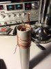
I hope this makes sence. Tommorow I can take assembly back down and take a pic of it. All connections have been made and recieve works excellant. It looks simmilar to a A99 coil set up.
Tried to upload a pic of A99 coil but it wont let me so I can only hope you know what it looks like.
.
I hope this makes sence. Tommorow I can take assembly back down and take a pic of it. All connections have been made and recieve works excellant. It looks simmilar to a A99 coil set up.
Tried to upload a pic of A99 coil but it wont let me so I can only hope you know what it looks like.
.
http://www.worldwidedx.com/attachment.php?attachmentid=13741&stc=1&d=1405558126
This is just a mock up of what we have.
Outside coil is connected to SO center to ant radiator
Inside coil is connected to sheild side of SO and Center pin SO
This is just a mock up of what we have.
Outside coil is connected to SO center to ant radiator
Inside coil is connected to sheild side of SO and Center pin SO
Attachments
Hi MR T , I like your radio I have a 2000 also with a Silver Eagle it looks sweet I recently switched to a SSk Mic an get a lot better reports on side band .
http://www.worldwidedx.com/attachment.php?attachmentid=13735&stc=1&d=1405555184
I hope this makes sence. Tommorow I can take assembly back down and take a pic of it. All connections have been made and recieve works excellant. It looks simmilar to a A99 coil set up.
Tried to upload a pic of A99 coil but it wont let me so I can only hope you know what it looks like.
Does the A99 coil that you could not post...look like this?

Is the coil in your post noted below, similar to what you are currently using on your CLR2? If so you are correct...it is more like the bottom part of the A99 matcher, and not what I see in the coil I sent you.

Just to be clear, is your next plan to make a coil like I sent?
Last edited:
Trying to get this coil perfectly tuned is going to be a difficult job for a few reasons. Replicating the original coil exactly is what's required to get it right. That includes everything from wire size to coil form diameter and spacing between turns.
To complicate things even more, the inductance of this coil will change every time you take the plastic cover on and off due to changes in the velocity factor so you won't be able to tune it exposed without the SWR changing when you put it back together.
For these reasons you might be better off changing the design of the matching network entirely. I'd consider something like what they use on the Maco V-58 since the network is exposed and easy to adjust. Just use a one turn loop from the radials to the bottom of the vertical and tap connection for the center of the coax connector towards the radial end of the loop for the best SWR.

You are correct Sir. Thanks for the comments on the 2000. I really like it and I use a RCI 2995DX as well. Both are great radios.
Yes it is my plan to replecate the coil you sent me but Im still curious on wheather the mock up (coil inside a coil) would have an effect on standing wave. Thats really what I need to find an answer for.
The coil you sent me was a working project wasnt it? If so what kind of SWR did you have with it.
Hope Im not a pain to you so far. All this trial and error adds up after a while and Id rather talk to some one with more experience than my self.
Shockwave, Thanks for your reply. I had thought about that myself but was hopeing to keep the CRL lookin original but that may not be an option.
I have been looking at V58 and penatrator designs as well thinking they might work but I was hoping to hear from someone elses ideas on it. I think I have duplicated the design Marconi sent me to use on my ant while were still experimenting on my neigbors. The whole thing is a learning experiance thats for sure.
I have been looking at V58 and penatrator designs as well thinking they might work but I was hoping to hear from someone elses ideas on it. I think I have duplicated the design Marconi sent me to use on my ant while were still experimenting on my neigbors. The whole thing is a learning experiance thats for sure.
Shockwave, Thanks for your reply. I had thought about that myself but was hopeing to keep the CRL lookin original but that may not be an option.
I have been looking at V58 and penatrator designs as well thinking they might work but I was hoping to hear from someone elses ideas on it. I think I have duplicated the design Marconi sent me to use on my ant while were still experimenting on my neigbors. The whole thing is a learning experiance thats for sure.
I'd encourage you to experiment. Remember that small changes can be made by spreading the coil apart or compressing the windings tightly together on the form. With some luck you might get the match quickly. If it starts driving you nuts, you see there are other options.
Im still curious on wheather the mock up (coil inside a coil) would have an effect on standing wave. Thats really what I need to find an answer for.
In case you haven't received an answer on this, yes it will effect the SWR. By placing one coil inside the other it makes the inside coil have less inductance since the diameter of each wrap is shorter. There are also changes in velocity factor having the coil inside the PVC. With each coil on opposite sides of the PVC, the coupling between them will also be reduced for the same number of wraps.
As you see in the Antron design, any of these changes can be made to work but each will require the exact inductance of the coils to be precisely altered to compensate for the changes in physical dimensions.
dxChat
- No one is chatting at the moment.