• You can now help support WorldwideDX when you shop on Amazon at no additional cost to you! Simply follow this Shop on Amazon link first and a portion of any purchase is sent to WorldwideDX to help with site costs.

home brewing a gain master ???

B

BOOTY MONSTER

Guest
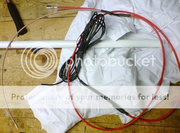
im not really interested in making a gain master , but i was wondering if anyone has thought about doing it . assuming there is no secret sauce in it it looks like its just coax with a RF invisible sleeve to hold the coax vertical and some metal at the bottom to attach to a mast . $180 plus S$H seems like an awful lot for some coax in a tube , but i could be wrong .
DSC00963.jpg


i was also curious about why sirios choke on the gain master has 15 plus turns on it . from what i understand 5 is optimal for the CB band

choke_impedances.png


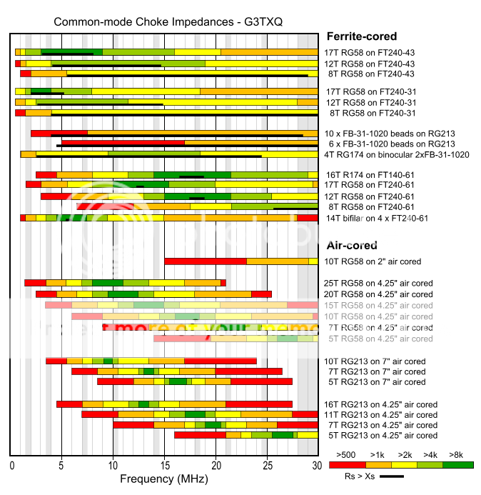
15 looks like it would be optimal for under 15 MHz. and least effective at 27 MHz. . possibly maybe even increasing CMC at 27 MHz. ???

LOL i wonder how long it will be till one of the CB antenna machinist make one with a top-hat or coil (or both) and one of their buddy's make a thread saying its 10-15 s-units stronger :) :) :) :)
 

booty, ive been wondering the same thing.

i would think that the piece of info we need is the velocity factor of the specific coax sirio uses.

i think that they have this coax specifically made for use in the gain master antennas. (thats why its red instead of grey or black IMO, because they could choose any color they wanted)

i think that the reason they have this coax specifically made is because it has a certain velocity factor that they can base their length calculations off of.

i would think that sirio knows that once this info is out there; people will be coming out of the woodwork with their own versions.

i hadnt given any thought to the coax choke, but you do make a good point.

i hope someone with more knowledge than i, can come here and explain this.
LC
 
I've considered it. Those are some of the unanswered details that prevents moving forward on it, yet. One could be built, but the results would stand in doubt no matter how well it worked without a real understanding of the actual components.
In all of the discussion I've read on it, there is a very healthy amount of speculation of how/why it works, but to date, I have missed any real breakdown of its details, or how they relate exactly to performance.

What if I threw one together? If it didn't work I'd not know why . . .
 
i was also curious about why sirios choke on the gain master has 15 plus turns on it . from what i understand 5 is optimal for the CB band

I might be wrong, but I thought that the number of turns depended on the diameter of the coil. And I agree that 180 bucks for some coax and a tube is a bit much. Trouble is, if the priced it low everyone would say, " It's just a cheap antenna".

- 399
 
I think we were all surprised to see the choke on the GM to be so effective with the coax size and number of coil wraps it has.

BM, the chart shows open-air chokes and not over a former so that may make some difference. I know very little about how chokes work, and have more or less gone along with what that chart you noted shows us. Maybe the whole issue of choking impedance is far more complicated than meets the eye and it is possible in our zeal to understand chokes we misjudged what we think we saw and read in that work by G3TXO.

Have you tried reading all the linking information on that website? That stuff is very technical, so maybe it's like a lot of things with CB'ers, we look at the pictures and get the wrong ideas and that is what we talk about as though it was gospel...without really understanding. I've tried this idea for making a choke and it did not seem to work for me. I have other cokes that showed to work on one installation, and not another. That corn'fused me.

I hear guys talk about using the Big Ugly choke and claim it works, and I've said it myself and heard it said...that choke coil is for much lower frequencies or multiband frequency operations. So, I don't know what the truth is after seeing what Sirio has done that proves to me to be very effective at decoupling the antenna from the feed line. I am amazed at what I see with that particular connection in the GM. When I modeled my version of an end fed 5/8 wave vertical radiator, without the tuning device attached, the results were remarkable how bad the pattern looked when I added a mast attached to the radiator without the choke and some way to decouple the feed line and radiator. Based on that view, I would say the antenna would not work at all. So, I've changed my mind regarding what and how a choke works. I'm back to not knowing at all. Hopefully my mentor on this issue will be able to explain all my confusion away. In the mean time I'm going back to my old mentors claim regarding feed lines. With a vertical antenna I try and always use a random length feed line that ends in some odd multiple of a 1/4 wavelength...rather than a 1/2 wavelength. He explained that this idea was approximately like using 18' feet in a CB mobile using coax with a velocity factor of .66%, or else you may have loading problems, etc. He was never one for many words.

As a practice in my radio work I always try and use a random length feed line that is not close to a tuned 1/2 wavelength or a multiple except in special cases. I say this even while I hear folks like Avanti, whom I respect very much, state to use 12' feet segments for .66% and 14' feet segments for .79% under special circumstances. Here again we see the words special circumstances. Wonder why Avanti talked about this specail use of a feed line? Could it have anything to do with the choking affects on a feed line? I'll leave the special circumstances idea to the fourm members to figure out as to why Avanti may have made such a claim in there antenna instructions.

Sorry BM, this is sort of a no-answer, answer.
 
Last edited:
BM, the chart shows open-air chokes and not over a former so that may make some difference. I know very little about how chokes work, and have more or less gone along with what that chart you noted shows us. Maybe the whole issue of choking impedance is far more complicated than meets the eye and it is possible in our zeal to understand chokes we misjudged what we think we saw and read in that work by G3TXO.
A choke is just an inductor, whether it's air wound on PVC or core wound on ferrite. The ferrite just adds to the permeability and increases the magnetic flux.
 
I've certainly considered a homebrew version, but the same questions Booty thought of I have been pondering over ever since this antenna hit the market. The G3TXO site I have read, and he used PVC waste pipe for the formers, and gives the dimensions of the formers on the graph, so they are basically air cored, unless the PVC has some sort of permeability, which I doubt it has. Maybe the Sirio GM has the aluminium bottom section through the middle of the choke? That would certainly affect the choke and maybe they found that adding more turns compensated for the aluminium within the plastic former they used? I'm just guessing here as I've only seen pics of the GM online.

From the pictures I've seen the matching stub looks to be made from RG178, which is not hard to get. The measurements that elude me are the value of the cap in the top half of the antenna, and the distance from the centre of the antenna that the cap is placed, also the same distance from the centre where the matching stub is placed. I'm guessing these measurements would be quite critical.

The red coax is intriguing, I just assumed it was 50 ohm coax, but maybe it isn't, someone who has a GM needs to help out on that.

It seems the people who have bought the GM have been very keen to get them up into the air as fast as possible, and rightly so, it's a lot of money to pay just to take some measurements and leave the antenna lying around. Hopefully someone soon will take the time to put the measurements we need online for all us homebrewers.

I was going to say I don't buy antennas, but that's not quite true because I only bought a yagi last week, but only because sadly it was cheaper than buying the parts to build one. If it is economically viable I always build my own antennas, it's just something I enjoy doing. I was thinking of substituting PVC for the fibreglass of the GM, it would sure be whippy, but it was just something I was considering for a /P antenna.

Like Homer said, it's easy to copy an antenna, if it didn't work after you copied it, then it would just be a pure case of trial and error to work out why it was not working as expected.
 
This is not going to be the easiest antenna to copy. Even if you had the same coax, copied the measurements exactly with the right capacitor, using this radiator in any other radome then the original will cause all of your measurements to shift. If the goal here is to truly see how good this antenna works, any little variables in the required electrical lengths due to velocity factors will cause obstacles that would complicate the build and leave you questioning if you got it right.
 
simon004 i put my PVC pipe and fittings in a 1000 watt microwave for 30 seconds and it didn't change temperature . from what i understand that doesn't mean that it is invisible to RF ..... but its a pretty good sign it can be used for RF insulating . i didn't have any issues using pvc tubing to hold the vertical on my home-brewed speaker wire starduster , which went into the pvc mast and i also used PVC to hold the bottom of the wire ground elements out .


good catch on the mounting plate possibly extending into the choke and requiring a different amount of turns to compensate . hopefully someone can shed some light on weather or not those two things are happening .

isn't the "radome" invisable to RF ? if it is how does it effect the radiator inside ? if it isnt how does the RF get through it to the radiator inside or out of it to TX ?
 
I have a quad here I made with PVC spreaders, and it seems to have no effect on how the antenna works at all. PVC, like fiberglass should be invisible to RF, so I hadn't really considered the effect of the radome, I just thought it wouldn't make a difference. I'm wrong often though, lol.

Albeit just a wire in a tube, this will be a very complex antenna to imitate, even if you do get a reasonable SWR, there is nothing to say your copy would be working as it should. There is only one way to find out though. I'm sure as hell not gonna buy one, but It'll be interesting to try and homebrew one.

You can make the spreaders for a quad out of many different insulating materials and it will not have much effect on the required wire length. There is a big difference when the radiation wire is encased inside a radome. When the RF has to pass through the insulator, it slows down and alters the physical length required. Almost no RF passes through the spreader on the quad.
 
You can make the spreaders for a quad out of many different insulating materials and it will not have much effect on the required wire length. There is a big difference when the radiation wire is encased inside a radome. When the RF has to pass through the insulator, it slows down and alters the physical length required. Almost no RF passes through the spreader on the quad.

I don't doubt you at all SW, If I do attempt to copy the GM it would be a PVC copy for sure, I aint gonna be buying any fiberglass I can guarantee that, lol, although I do have an A99 here doing nothing. I could rip the guts out of that and put something else inside, but building one would just be an exercise in seeing if I could do it or not. PVC appears to have no effect on RF, but like you say, I've never put a radiating element inside it to truly find out.
 
how does the RF slow down ?
if the RF travels slower is it moving at a slower/lower frequency ?

LOL , im sure im not understanding what you mean about the RF slowing down .
could you explain that a little ?
 
how does the RF slow down ?
if the RF travels slower is it moving at a slower/lower frequency ?

LOL , im sure im not understanding what you mean about the RF slowing down .
could you explain that a little ?

Think of velocity factor relating to the speed at which the RF travels through a given medium. In a vacuum, RF has the same speed as light. Through some coax cables it may only travel at 66% of that speed. This does not effect the frequency, only the time it takes the signal to travel through the cable. It will arrive at the other end at the same frequency, it will just be delayed by the velocity factor.

If someone claps their hands once a second and you are listening from 1000 feet away, the clap is still once a second. It just takes a little time for the sound to travel through 1000 feet of air as the medium and reach you at this distance. I hope that analogy works as an explanation.
 
  • Like
Reactions: 2 people

dxChat
Help Users
  • No one is chatting at the moment.
  • @ Wildcat27:
    Hello I have a old school 2950 receives great on all modes and transmits great on AM but no transmit on SSB. Does anyone have any idea?
  • @ ButtFuzz:
    Good evening from Sunny Salem! What’s shaking?
  • dxBot:
    63Sprint has left the room.
  • dxBot:
    kennyjames 0151 has left the room.