
You are using an out of date browser. It may not display this or other websites correctly.
You should upgrade or use an alternative browser.
You should upgrade or use an alternative browser.
-
You can now help support WorldwideDX when you shop on Amazon at no additional cost to you! Simply follow this Shop on Amazon link first and a portion of any purchase is sent to WorldwideDX to help with site costs.
-
A Winner has been chosen for the 2026 July 4th Retevis RA89R Giveaway! Click Here to see who won!
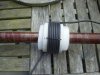
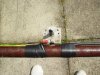
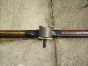
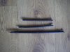
Variable plate cap try and coax caps tried
few more pics, quite easy this way thanks for the advice, what is the basic fundemental desciption of this antenna design? as it is not just a vertical .64 wave, I have seen similar types for VHF with stub matching and coax caps and I think they were end fed stacked dipoles?
Phil
few more pics, quite easy this way thanks for the advice, what is the basic fundemental desciption of this antenna design? as it is not just a vertical .64 wave, I have seen similar types for VHF with stub matching and coax caps and I think they were end fed stacked dipoles?
Phil
Attachments
question if i might?
looking at the above drawing for the GM...so if running something with a coax choke already incorporated into the design of the antenna, would adding one to the coax be redundant? i'm about to lift my 2012 and i believe it follows the same design element
thanx
Hey Whiplash, just had a look at a 2012 out of curiosity and it looks like an enclosed RF tuning coil at the base not an ugly balun as they are called? others on here may have better idea, but if you have problems with tvi I would give it go it worked well for me with only 5 coax turns on a 9cm former.
73
Phil
Hi Marconi, just tried a coax choke/Ugly balun coil with thiner coax on a 6cm (slighly less than on the plans) former and it comes close to your coil legnth and the 331.5cm coax run given on the plans so it is mm that are the diamensions given, rain has stopped play here "again" going to try the full sized 16 turn coax balun once a former of the right outer diameter is found and also do it in one run of coax from the swr meter up to the bobtail 1/4 wave 50 ohm shunt which will be on a T piece for easy changing while experimenting as I am sick of soldering, this must be possible with cheaper coax for lower power use.PhilipB, how can the length of the coil former added in at the bottom of the image above be 331,5 mm tall?
Phil
coax capacitance
Dont ask me the whole thing has me bamboozled:blink: I read a thread on a physics forum about coax capacitance and it seems there are many variables to consider and the makers of coax only quote the capacitance for the coax at very low frequency levels so by the time you get to 27mhz it is totaly different? thats why Im shouting for help lol.
If you get any good ideas please share them.
As I said before I think this antenna realy does have some voodoo in it.
Phil.
Go HERE and scroll to RG303 and you'll find it's 29.4pf per foot.
9cm is 3.54"
3.54" ÷ a foot(12") = .295 feet
.295 x 29.4 = 8.67pf, not 15pf
What am I missing?
Dont ask me the whole thing has me bamboozled:blink: I read a thread on a physics forum about coax capacitance and it seems there are many variables to consider and the makers of coax only quote the capacitance for the coax at very low frequency levels so by the time you get to 27mhz it is totaly different? thats why Im shouting for help lol.
If you get any good ideas please share them.
As I said before I think this antenna realy does have some voodoo in it.
Phil.
Hey Whiplash, just had a look at a 2012 out of curiosity and it looks like an enclosed RF tuning coil at the base not an ugly balun as they are called? others on here may have better idea, but if you have problems with tvi I would give it go it worked well for me with only 5 coax turns on a 9cm former.
73
Phil
appreciate the feedback, thanx!!
HB GM
I knew I had seen something similar to this before, here is a similar Home Brew coax stub matched antenna for 5/8wl on 20m (dont understand any of this either lol)
Matching a 5/8» vertical - example 1
Phil
I knew I had seen something similar to this before, here is a similar Home Brew coax stub matched antenna for 5/8wl on 20m (dont understand any of this either lol)
Matching a 5/8» vertical - example 1
Phil
very interesting from your article above philip
"If the radiation pattern of a vertical monopole over a perfectly conducting ground is studied, at a little over λ/2, the main lobe divides. This point is often taken as 5/8λ (0.625λ), but it is just a little less. So, in practice, a radiator of 0.6λ is quite sufficient."
From the measurements on the pic/plans you posted, i came up with a total length of 22.31 feet which ends up being .62 wl.
best of luck, work has me tied up pretty good and I will be on the road starting tomorrow evening until next week,,,but I will check in today and tomorrow before leaving.
Sorry I haven't been stopping in as much but I'll try and address a few of the questions that have popped up lately. Booty, the radome on the GM causes the electrical length of the conductor to appear shorter then it is physically just like the 96 inch fiberglass whip. While many marine fiberglass antennas will use spacers inside the radome to keep the wire centered, this is not required. As the wire moves closer to the radome on one side, it also moves equally further from the other side. Thereby not causing a noticeable shift in velocity. I can confirm no amount of wind blowing ever changes the near flat VSWR I see from 25.7 to 29.7 Mhz.
Let's think about why this antenna uses more wraps in its choke then we are familiar with. Remember the base of the GM is energized with RF just like the top. While the inside of the coax is 50 ohms, the radiated RF coming down the braid on the GM is a much higher impedance because it's more then a 1/4 wave down from the electrical center feedpoint. I suspect more then simple choking action is taking place to remove this high RF voltage on the shield of the connector as someone else eluded to here.
What would happen if we not only choked off the RF but took the time to design the choke to create a desired phase shift to the RF on the outside of the coax so that the choke was no longer placed in such a high impedance path? We have about a 115 degree phase shift in radiation currents between the center feed down to the top of the choke. I suspect an attempt has been made to add another 65 degrees of phase shift within the choke so that it now works in a low impedance point, 180 degrees away from the source.
The orange coax on the GM appears to be 50 ohm foam dielectric. The only odd thing I spot here is it has black foam insulation but I doubt this makes a difference. The issue I've found is that some cables with the same numbers can advertise a different velocity factor from one manufacturer to another. Meaning the same physical length may not produce the same electrical length or capacitance. That can screw everything up from the value of the cap to the location and length of the tuning stub on the bottom coax.
The capacitor is quite low in pf value. I once mentioned in another forum that the tolerance of this cap should be held to within .25 pf and was told that was impossible. The gentleman refused to understand this was about 3% of the total value and not some impossible tolerance or value to achieve. The value is 8.7 pf, no where near 15 pf. Most air variables with aluminum plates won't tune this low. The tiny trimmer caps used to pad crystals often tune this range. Problem is the RF voltage at this point is much higher then you would be expecting. More then 2000 volts will be present above 600 watts and about 1000 volts at 150 watts.
Problems with VSWR can be traced to any one of a number of issues in this homebrew design. If adjusting the value of the cap and single conductor wire above it do not make it resonant in the correct place, remember the length of coax below the cap is just as important and will vary with different cables. The velocity factor here will also change the physical location of the tuning stub.
I consider myself fairly skilled at antenna building and the GM is not one antenna I would feel confident in knowing it had been built 100% correct without an accurate comparison against the real McCoy. I don't say this to discourage anyone from trying this, just be aware there are several areas where one can go wrong and not obtain the desired performance. Most antennas only have the main radiator length and perhaps a tap on an inductor to adjust its resonant point.
The GM is far more complex with its cap value, length of orange coax, length of top black wire, length and positioning of the coax stub and last but not least, proper cutoff of the radiation within the RF choke. Many of these perimeters can be off and you'll still be able to get a match by compensating elsewhere. Except you'll be missing the full performance unless all elements of this antenna are tuned properly.
PS: YES! The Vector 4000 radiates from the base cone and does so in a phase that is constructive to the main radiator. That's why it outperforms the 1/2 wave it would be if the cone did not radiate. When was the last time you heard an operator claim his Antron 99 performed like his Vector 4000?
Last edited:

If homebrewing a GM, is there really a need to use the same type of RF choke, surely a torroid type choke would perform the function much better, and with a higher choking impedance?
As for the Vector 4000, I'm sure the debate will continue, opposing currents tend to cancel each other out, what is it about the cone on the Vector 4000 that goes against this accepted theory?
As for the Vector 4000, I'm sure the debate will continue, opposing currents tend to cancel each other out, what is it about the cone on the Vector 4000 that goes against this accepted theory?
If homebrewing a GM, is there really a need to use the same type of RF choke, surely a torroid type choke would perform the function much better, and with a higher choking impedance?
As for the Vector 4000, I'm sure the debate will continue, opposing currents tend to cancel each other out, what is it about the cone on the Vector 4000 that goes against this accepted theory?
35, I have never heard anyone claiming to own a GainMaster report...the antenna produced symptoms of common mode currents flowing below the choke or produced detectable TVI/RFI, have you?
In fact what I've heard is the exact opposite. My personal experience using my GM for over a year now...indicates the same. My GM is the best behaved 11 meter vertical I have in this regard and I noticed that feature right off the bat.
With that said, why try and fix a problem that doesn't exist?
Concerning your thoughts on the V4000 and the proper currents flowing in the radial basket area of the antenna. I believe your claim for cancellation is correct, opposing currents do tend to cancel. But, what is your thinking about what might be going on in the bottom of the Vector, and in particular, what do you use to make such a judgment as to whether the currents are opposing or not? What would it take to convince someone the radial cone radiated or not?
We can't see currents flowing, so we have to depend on something else to give us insight into that activity. What indicates to you that the currents are flowing properly or not in the V4000?
I've heard more than a few claim to have a way to prove once and for all, but none thus far have ever done any work to prove this idea beyond a doubt. I go by what my Eznec modeling shows me, but most on this forum don't have any confidence in modeling. If that would be of help to you, let me know and I'll post some comparisons to consider, and let the naysayers be hanged.
How say you?
Last edited:
If we are discussing homebrewing a GM, and the complexities of the choke and what it may or may not be doing, then adding a torroidal choke would not only simplify construction, but be an effective choke to boot, I'm not questioning the Sirio version ")
As for modelling, I have every faith in a well designed model, anything you've got would be of interest.
As for modelling, I have every faith in a well designed model, anything you've got would be of interest.
If we are discussing homebrewing a GM, and the complexities of the choke and what it may or may not be doing, then adding a torroidal choke would not only simplify construction, but be an effective choke to boot, I'm not questioning the Sirio version
As for modelling, I have every faith in a well designed model, anything you've got would be of interest.
You might be right considering a home brew...that it is easier to construct a GM with a toroid choke. I wouldn't try it, but maybe you would. Are you considering such a project?
I have a model for a stacked 5/8 wave collinear using a phasing stub that demonstrates the collinear function and the phase relationship between the two 5/8 wave radiators that allows it to produce a nice gain on the horizon, via constructive RF contribution in current distribution.
I would use this as a base line comparison using the Eznec tabular Current Report to show the currents magnitude and phase...as compared to the same on my current model for a Sigma4 and you be the judge.
Both reports suggest a constructive phased relationship that in combination adds gain. Some claim the Vector cone cancels out, due to being out of phase with the top 1/2 wave radiator, and thus the Vector/Sigma4 is only a 1/2 wave antenna. I have asked how such is determined before, but I don't recall a single feasible reply.
IMO, the Vector/Sigma4 are fully in phase between the bottom cone and the upper 1/2 wave, and thus they are both produce a full 3/4 wave radiating element pattern that shows to produce improved gain at a very low angle to the horizon and over Eznec's real Earth feature.
I can't tell you that in my real world testing, that I've even noticed a detectable difference among the various antennas I've tested at my location, but my modeling shows there is a bit of a difference with maybe a 1 degree lower maximum angle at most heights.
Attached is an overlay for several CB antenna patterns indicating the Sigma4 with superior gain and pattern at only 9' feet above Earth. At higher elevations this difference may be somewhat more similar accross the board.
View attachment CB antennas compared..pdf
dxChat
- No one is chatting at the moment.