B
BOOTY MONSTER
Guest
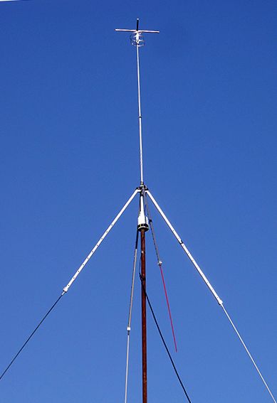
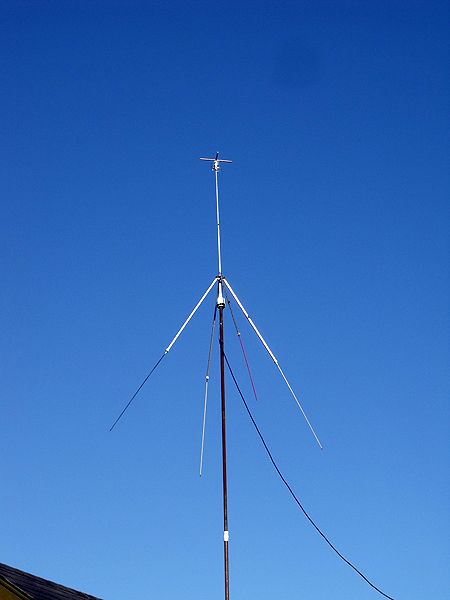
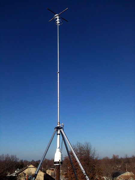
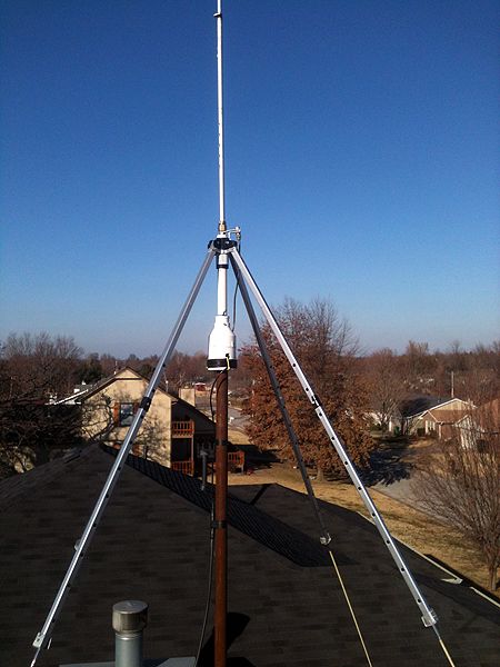
a different ground element angle is why i want to try another star-duster down the road . my first one had 45 degree ground elements but (somewhere) i recall marconi posting a link to the star-duster stating that the angle of the ground elements is important and that i should have had a steeper angle . i don't expect much difference , but it's on the to do list DTR .